

Communication equipment metal shell and preparation method thereof
A technology for communication equipment and metal shells, which is applied in the field of metal shells of communication equipment and its preparation, can solve the problems of poor matrix strength and shell deformation, and achieve the effects of improving processing strength, avoiding deformation, and good decoration and protection
- Summary
- Abstract
- Description
- Claims
- Application Information
AI Technical Summary
Problems solved by technology
Method used
Image

Examples
preparation example Construction
[0044] The present invention also provides a method for preparing a metal casing of a communication device, wherein the method includes the following steps:
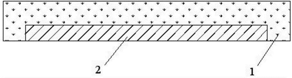
[0045] 1) injecting resin on at least a part of the inner surface of the metal substrate to form a plastic support layer;
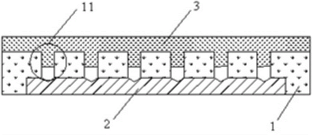
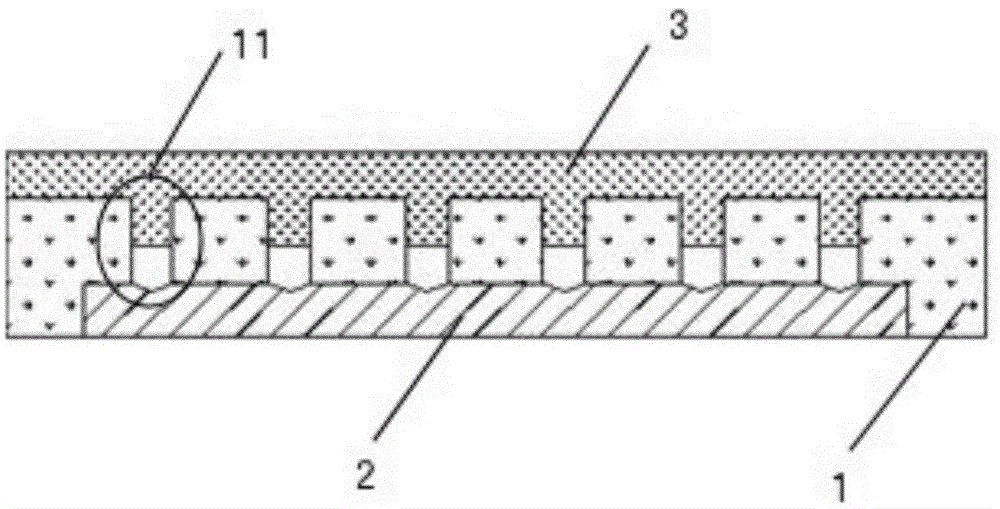
[0046]2) More than one slit is formed in the area of the metal substrate where the plastic support layer is formed, and the slit penetrates the metal substrate and does not penetrate the plastic support layer.
[0047] According to the present invention, the thickness of the metal substrate and the thickness of the plastic supporting layer are not particularly limited, and those skilled in the art can make appropriate selections according to specific communication devices. For example, the thickness of the metal substrate may be 0.1-0.6 mm, preferably 0.2-0.5 mm; the thickness of the plastic support layer may be 1-2 mm, preferably 1.2-1.8 mm.
[0048] According to the invention, the resin is pref...
Embodiment 1
[0069] 1) Injection molding on one surface of the metal substrate
[0070] An aluminum alloy (purchased from Dongguan Gangxiang Metal Materials Co., Ltd., grade 6063, thickness 0.6 mm) was cut into a size of 15 mm x 80 mm as a metal substrate. Degreasing and washing with water were performed on the above metal substrate to remove surface stains and oil stains, and then dried at 80°C for 20 minutes to obtain the cleaned and dried metal substrate A11.
[0071] Put the above metal substrate A11 into a mold, and use polyphenylene sulfide resin to inject the inner surface of the metal substrate A11. Injection molding conditions are: mold temperature 280°C, nozzle temperature 400°C, holding time 30s, injection pressure 260MPa, injection time 20s, delay time 20s, cooling time 40s, forming a plastic support layer (thickness 2.0mm), so as to obtain Metal housing A12 with injection molded support layer.
[0072] like figure 1 As shown, the metal casing A12 with the injection molded s...
Embodiment 2
[0081] 1) Injection molding on one surface of the metal substrate
[0082] An aluminum alloy (purchased from Dongguan Gangxiang Metal Materials Co., Ltd., grade 6063, thickness 0.6 mm) was cut into a size of 15 mm x 80 mm as a metal substrate. Degreasing and washing with water were performed on the above metal substrate to remove surface stains and oil stains, and then dried at 80°C for 20 minutes to obtain the cleaned and dried metal substrate A21.
[0083] The metal substrate A21 is put into a mold, and polyphenylene sulfide resin is used to inject the inner surface of the metal substrate A21. The injection molding conditions are: mold temperature 80°C, nozzle temperature 230°C, holding time 5s, injection pressure 70MPa, injection time 3s, delay time 3s, cooling time 5s, forming a plastic support layer (thickness 1mm), so as to obtain a The metal casing of the support layer A22.
[0084] 2) Form a slit
[0085] Adopt a laser drilling machine (the model produced by Huagong...
PUM
| Property | Measurement | Unit |
|---|---|---|
| depth | aaaaa | aaaaa |
| thickness | aaaaa | aaaaa |
| thickness | aaaaa | aaaaa |
Abstract
Description
Claims
Application Information