Supercharge Your Innovation With Domain-Expert AI Agents!

clamping spring

A technology of clamping springs and clamping edges, which is applied in the direction of clamping/spring connection, fixed connection, electrical components, etc.

Active Publication Date: 2018-01-05
PHOENIX CONTACT GMBH & CO KG
View PDF6 Cites 0 Cited by
  • Summary
  • Abstract
  • Description
  • Claims
  • Application Information

AI Technical Summary

Problems solved by technology

In order to open the spring an additional guide usually has to be provided, which results in additional expenditure

Method used


Image

  • clamping spring
  • clamping spring
  • clamping spring

Examples


Embodiment Construction

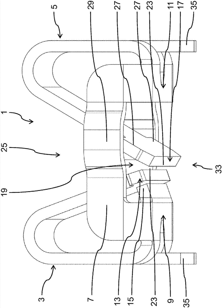
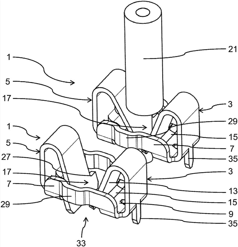
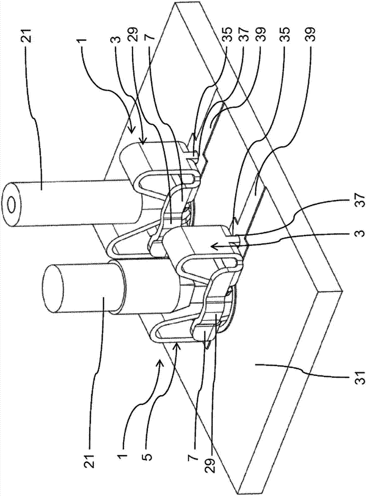
[0028] figure 1 and 2 A clamping spring 1 according to the invention according to a first preferred embodiment is shown. The clamping spring 1 is formed as a one-piece plate-shaped part from spring steel with galvanic copper coating and tin plating and is produced by stamping and bending.

[0029] The clamping spring 1 comprises a fixed clamping leg 3 , a spring leg 5 and two guide parts 7 . The guide part 7 is designed as a connecting part, which is connected to the end 9 of the clamping leg 3 and the end 11 of the spring leg 5 .

[0030] The clamping edge 3 is formed as an essentially elongated plate-shaped part bent in the shape of a hook and loop such that its two ends 9 , 13 approach each other. Such as figure 1 As shown in detail in , the clamping leg 3 has on its fixed end 9 a projection 15 designed as a clamping part and forms a clamping clamp for the other free end 13 of the clamping leg 3 .

[0031] The elastic side 5 is also formed as a substantially elongated ...


PUM


Abstract

The invention relates to a clamping spring (1) for mounting on a circuit board (31), comprising an elastic edge (5) for contacting a conductor (21) in clamped form, for contacting a circuit board (31 ), wherein the clamping spring (1) is formed in one piece, the elastic side (5) has an actuating part (27) for unclamping, and the clamping spring (1) has The guide part ( 7 ) is arranged in such a way that a tool for actuating the operating part ( 27 ) can be inserted between the spring edge ( 5 ) and the guide part ( 7 ). The invention furthermore relates to a circuit board (31) having a conductor track (39) and the aforementioned clamping spring (1), wherein the clamping spring (1) is electrically conductively connected to the conductor track (39).

Description

technical field [0001] The invention relates to a clamping spring for mounting on a circuit board and to a circuit board with conductor tracks and such a clamping spring. Background technique [0002] In the assembly of circuit boards, it is now common to automatically glue and adhere small or smallest components to the circuit board to be soldered to the circuit board in a subsequent process. [0003] Large terminal clips generally cannot be integrated in this process but are introduced onto the circuit board later in a hand soldering process. This step requires increased costs. Often only a single conductor needs to be connected to a conductor track of a circuit board or to a device, so automated methods developed for terminal clips cannot be effectively implemented. [0004] A clip is known from DE 20 2009 006 254 Ul, which is fastened to a printed circuit board in the form of a Lowe sleeve. Correspondingly contacting boreholes are provided on the printed circuit board...

Claims


Application Information

Patent Timeline
Patent Type & Authority Patents(China)
IPC IPC(8): H01R4/48H01R12/75
CPCH01R12/75H01R4/4848H01R4/4823H01R12/57
Inventor 于尔根·法伊-霍曼
Owner PHOENIX CONTACT GMBH & CO KG
Features
  • R&D
  • Intellectual Property
  • Life Sciences
  • Materials
  • Tech Scout
  • Unparalleled Data Quality
  • Higher Quality Content
  • 60% Fewer Hallucinations
Learn More