

Circular-disc type precision drill seeding device of small-seed crops
A small-grain, disc-type technology, used in planting methods, sowing planters, planter parts, etc., can solve problems such as difficulty in thinning, lack of seedlings, ridge breakage, and many seedlings, and achieve convenient seed replenishment, disassembly, and location. accurate effect
- Summary
- Abstract
- Description
- Claims
- Application Information
AI Technical Summary
Problems solved by technology
Method used
Image

Examples
Embodiment Construction
[0024] Below in conjunction with specific examples, the disc-type precision drilling device for small-grain crops of the present invention will be further described, so that those skilled in the art can better understand the present invention and can implement it, but the examples given are not intended as a reference to the present invention. limit.
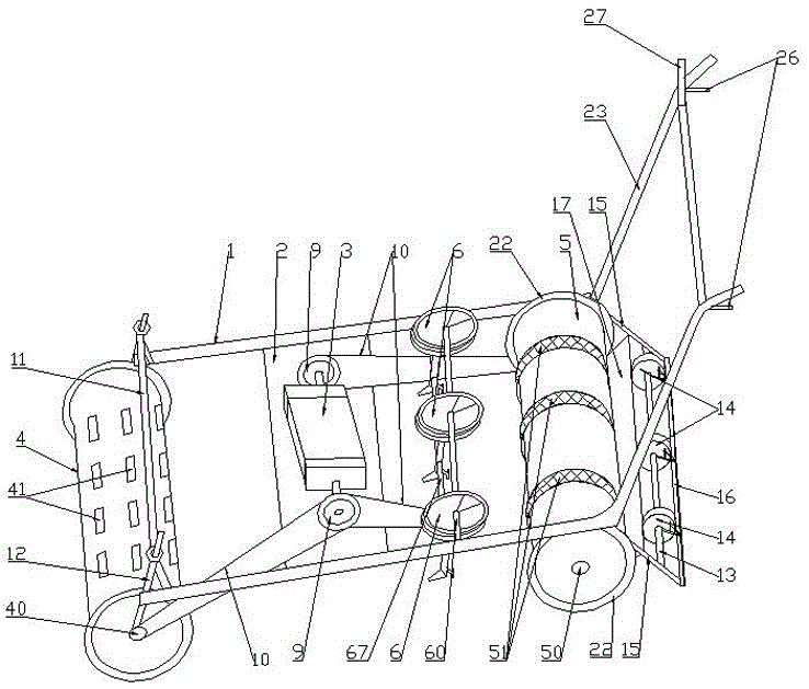
[0025] A disc-type precision drill device for small-grain crops, such as figure 1 As shown, the device includes a bracket 1, a support 2 for fixing the engine 3, a front drum 4, a rear drum 5, a plurality of seeding mechanisms 6, and a power supply for the front drum 4, the rear drum 5, and the seeding mechanisms 6. Engine 3, the rear end of support 1 is provided with handrail 23, and the front end of support 1 is provided with horizontal lifting plate 11, and front cylinder 4 plays smooth ground and suppression function, can lift front cylinder 4 by horizontal lifting plate 11.
[0026] Wherein, the front cylinder 4 and the re...
PUM
 Abstract
Description
Claims
Application Information