Laboratory gas collecting device

A collection device and laboratory technology, which is applied in the field of laboratory gas collection devices, can solve problems such as hidden dangers and the safety of organic gases, and achieve the effect of improving safety

Inactive Publication Date: 2016-05-04
NINGBO DINGYUAN SOFTWARE TECH CO LTD
View PDF0 Cites 0 Cited by
  • Summary
  • Abstract
  • Description
  • Claims
  • Application Information

AI Technical Summary

Problems solved by technology

[0003] The main purpose of the present invention is to solve the techn

Method used


Image

  • Laboratory gas collecting device
  • Laboratory gas collecting device

Examples


Embodiment Construction

[0013] The present invention will be further described below in conjunction with the accompanying drawings and specific embodiments.

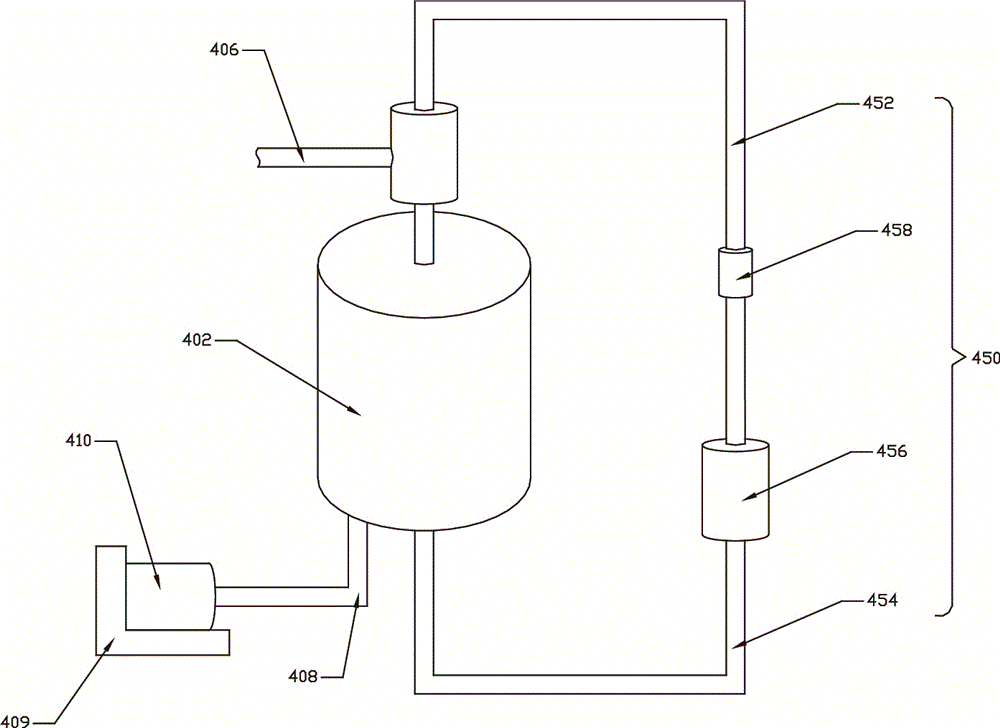
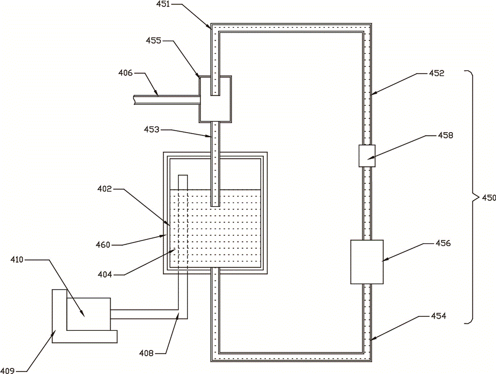
[0014] See Figure 1 to Figure 2 , In one embodiment, the laboratory gas collection device includes a tank 402, a cooling liquid 404 contained in the tank 402, a cooling liquid circulation system 450 connected to the tank 402, connected to the The air intake pipeline 406 of the tank body 402, the exhaust pipeline 408 connected to the tank body 402 and the gas storage device 410 connected to the exhaust pipeline 408, the cooling liquid circulation system 450 includes The liquid injection pipeline 452 at one end of the tank body 402 and the liquid discharge pipeline 454 connected to the other end of the tank body 402, the air intake pipeline 406 communicates with the liquid injection pipeline 452, and the exhaust pipe One end of the road 408 extends out of the cooling liquid 404 through the liquid surface of the cooling liquid 404 in the tank bo...


PUM


Abstract

The invention discloses a laboratory gas collecting device. Capture, separation and collection of an organic gas under a low temperature environment are realized through the communication of a tank, cooling liquid, a cooling liquid cycling system, a gas inlet pipeline, a gas discharge pipeline and a gas storage device, and the production operation safety is greatly improved; a firming device is arranged below the gas storage device, thus preventing the condition that gas collection is too quick and gas pressure is too large so that the gas storage device is thrust aside.

Description

technical field [0001] The invention relates to the technical field of organic gas collection, in particular to a laboratory gas collection device. Background technique [0002] In the preparation process of existing chemical products, some by-products are often produced, and these by-products need to be separated. When the auxiliary product is organic gas, the organic gas must be captured first, and then the captured organic gas should be transported to the separation device. The existing ones are generally captured and transported by high-temperature and high-pressure compressors, and then the organic gas can be collected. , and the chemical properties of organic gases are generally unstable; accidents such as explosions are prone to occur in high-temperature and high-pressure environments, which makes the existing organic gas collection methods more dangerous and has potential safety hazards. Contents of the invention [0003] The main purpose of the invention is to so...

Claims


Application Information

Patent Timeline
IPC IPC(8): B01L5/02B01D53/18B01D53/00
CPCB01L5/02B01D53/002B01D53/1487B01D53/18B01D2257/70B01D2258/02
Inventor 张勤洲
Owner NINGBO DINGYUAN SOFTWARE TECH CO LTD
Why Eureka
Try Eureka