Heating device of injection molding machine

A technology for an injection molding machine and a heating device, which is applied to the field of heating devices, can solve the problems of temperature control response decline, controllability decline, difficulty in adding a cooling structure heating function and cooling function, etc., and achieves response decline suppression and controllability The effect of drop suppression

Active Publication Date: 2016-05-04
NISSEI PLASTICS IND CO LTD
View PDF8 Cites 3 Cited by
  • Summary
  • Abstract
  • Description
  • Claims
  • Application Information

AI Technical Summary

Problems solved by technology

[0008] First, there is a disadvantage that the heating structure is basically sacrificed in the structure in which a cooling pipe is wound between the heating heater and the heating cylinder to allow the cooling water to flow as in Patent Document 1.
That is, the heating structure heats the heating cylinder by transferring the heat of the heating heater to the heating cylinder. Therefore, interposing a member (cooling pipe) that inhibits heat transfer between the heating heater and the heating cylinder will increase heat loss. , which in turn greatly reduces the heating efficiency, and will lead to a decrease in the responsiveness and controllability of temperature control
Therefore, it is not suitable for use for materials that require active melting such as thermoplastic resins
[0009] On the other hand, as in Patent Document 2, the heater attached to the outer peripheral surface of the heating cylinder is blown by the fan from the outside of the heater. On the contrary, the heater is interposed between the fan and the heating cylinder. , so it will hinder the air-cooling effect, which will lead to a significant drop in air-cooling efficiency
In addition, since a fan or the like needs to be placed near the heating cylinder, it will lead to unnecessary enlargement of the molding equipment and decrease in space efficiency.
[0010] As a result, in the case of a structure in which a heater is attached to the outer peripheral surface of the heating cylinder to directly transfer heat from the heater to the heating cylinder for heating, the actual situation is that it is difficult to add a cooling structure to fully exert both the heating function and the cooling function. function, so one of them had to be sacrificed

Method used


Image

  • Heating device of injection molding machine
  • Heating device of injection molding machine
  • Heating device of injection molding machine

Examples


Embodiment Construction

[0034] Next, preferred embodiments of the present invention will be listed and described in detail based on the drawings. In addition, the drawings do not limit the present invention, but are for facilitating understanding of the present invention. In addition, in order to avoid ambiguity of the invention, detailed descriptions of known parts are omitted here. .

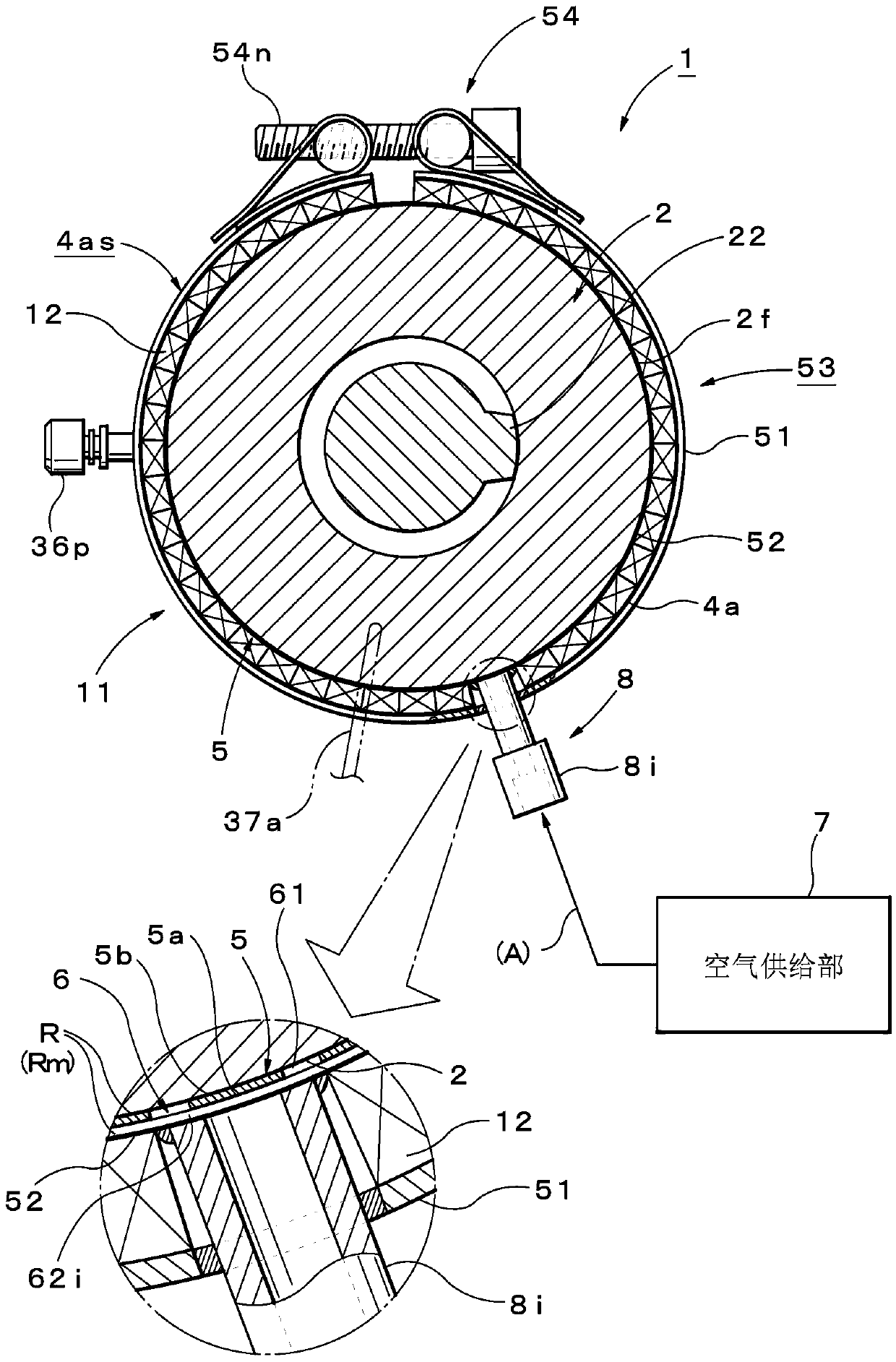
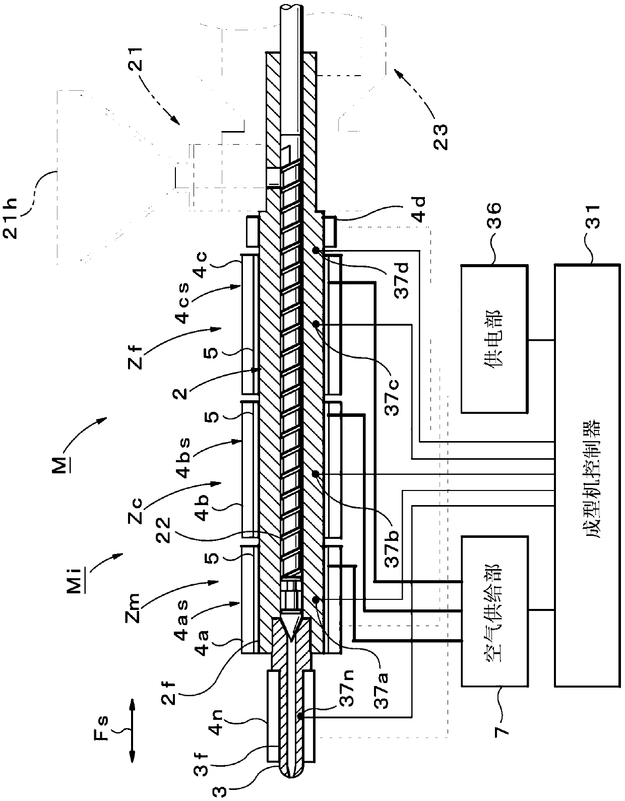
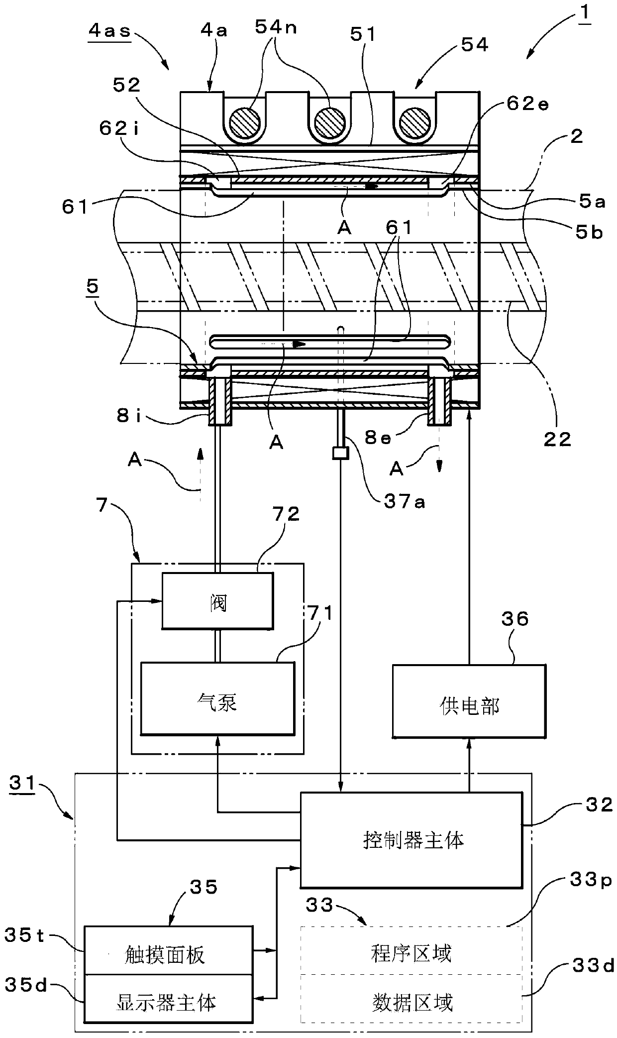
[0035] First, refer to Figure 1 to Figure 7 , the structure of the heating device 1 of the injection molding machine M of this embodiment will be described.

[0036] exist figure 2 Here, Mi is an injection device, and the injection molding machine M is composed of the injection device Mi and a mold clamping device not shown. The injection device Mi has a heating cylinder 2 having an injection nozzle 3 at the front end, and the rear end of the heating cylinder 2 is combined with a material supply part 21 having a function for supplying molding to the inside of the heating cylinder 2. Material funnel 21h. In ad...


PUM


Abstract

The invention provides a heating device of an injection molding machine. When a heating device is formed which includes at least one or more heaters (4n, 4a, 4b, 4c and 4d) that are provided on the outer circumferential surfaces (2f and 3f) of at least one of a heating cylinder (2) and an injection nozzle (3) to heat at least one of the heating cylinder (2) and the injection nozzle (3), at least some heaters (4a, 4b, 4c, . . .) of all the heaters (4n, 4a, . . .) are formed with air cooling-capable heaters (4as, 4bs and 4cs) in which a panel member (5) formed of a material having thermal conductivity is interposed between the heaters (4a, 4b, 4c, . . .) and the outer circumferential surfaces of at least one of the heating cylinder and the injection nozzle, in which an air path (6) for air cooling is formed in the panel member (5) and in which an air outlet and inlet portion allowing air to be passed from an air supply portion is provided in the air path.

Description

technical field [0001] The present invention relates to a heating device for an injection molding machine including a heater attached to an outer peripheral surface of a heating cylinder and the like to heat a heating cylinder and the like. Background technique [0002] Generally, an injection molding machine has an injection device for injecting molten resin into a mold. In this case, the injection device has a heating cylinder having an injection nozzle at the front end and a funnel at the rear, a screw inserted through the inside of the heating cylinder, and a heating cylinder attached to the outer peripheral surface of the heating cylinder. device (heater). Thus, the solid-shaped pellets supplied from the hopper to the inside of the heating cylinder are plasticized and mixed by the shearing by the rotation of the screw and the heating of the heating cylinder, thereby producing molten resin for injection filling into the mold. . On the other hand, from the viewpoint of...

Claims


Application Information

Patent Timeline
IPC IPC(8): B29C45/74
CPCB29C45/74B29K2101/12
Inventor 樱田勇一加藤利美户泽启一
Owner NISSEI PLASTICS IND CO LTD
Why Eureka
Try Eureka