
Double-source electric locomotive converter

A technology for electric locomotives and converter devices, applied in electric vehicles, electric traction, traction of DC motors, etc., can solve the problems of catenary burning, transformer volume and weight, damage to phase separation devices, etc., and save electric energy. , the effect of reducing volume and weight

Active Publication Date: 2016-05-04
ZHUZHOU CSR TIMES ELECTRIC CO LTD
View PDF5 Cites 12 Cited by
  • Summary
  • Abstract
  • Description
  • Claims
  • Application Information

AI Technical Summary

Problems solved by technology

The above-mentioned two kinds of over-phase operation methods of "human control" and "machine control" are difficult to eliminate the phenomenon of over-phase phase due to the possible mistakes of the operators and equipment failures. Once it occurs, the pantograph, The phase separation device is damaged, and in severe cases, it will cause catenary burning, interrupt railway transportation, and pose a serious threat to the safety of electrified railways
[0003] At the same time, traditional electric locomotives only rely on the catenary for power supply. In areas without grids, such as the northern plateau, the advantages of electric locomotives cannot be brought into play.
The traction power of traditional high-power electric locomotives is provided by the 25kV catenary, which is transformed into the power required by the traction load through the traction transformer. If the entire vehicle power is provided by the traction transformer, the volume and weight of the transformer are relatively large. Relatively difficult to install

Method used


Image

  • Double-source electric locomotive converter
  • Double-source electric locomotive converter
  • Double-source electric locomotive converter

Examples


Embodiment Construction

[0032] The following further describes the present invention with reference to the accompanying drawings of the specification and specific preferred embodiments, but the protection scope of the present invention is not limited thereby.

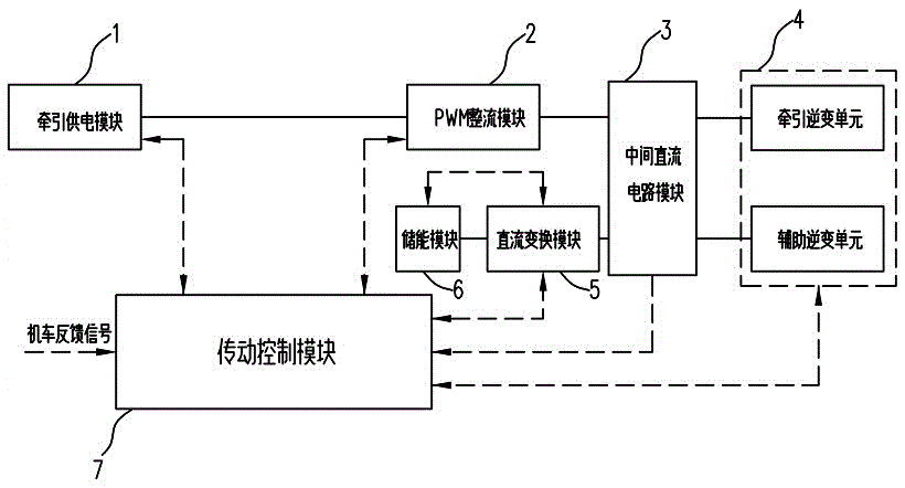
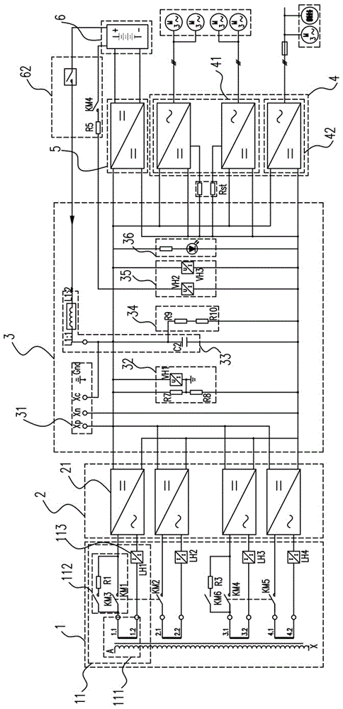
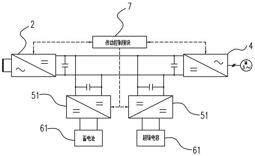
[0033] Such as figure 1 As shown, a dual-source electric locomotive converter device in this embodiment includes a traction power supply module 1, a PWM rectifier module 2, an intermediate DC circuit module 3, an inverter module 4, a DC conversion module 5, an energy storage module 6 and a transmission Control module 7; the grid-side input port of the traction power supply module 1 is connected to the power supply grid, the output port of the traction power supply module 1 is connected to the AC side port of the PWM rectifier module 2; the DC side port of the PWM rectifier module 2 is connected to the intermediate DC circuit module 3 The intermediate port of the inverter module 4 is connected to the DC bus of the intermediate DC circuit module 3; ...


PUM


Abstract

The invention discloses a double-source electric locomotive converter. The double-source electric locomotive converter comprises a traction power supply module, a PWM rectifying module, an intermediate direct-current circuit module, an inversion module, a direct-current conversion module, an energy storage module and a transmission control module; a network side input port of the traction power supply module is connected with a power supply grid, and an output port of the traction power supply module is connected with an alternating-current side port of the PWM rectifying module; a direct-current side port of the PWM rectifying module is connected with a direct-current bus of the intermediate direct-current circuit module; an intermediate side port of the inversion module is connected with the direct-current bus of the intermediate direct-current circuit module; an output side port of the inversion module is connected with electric equipment; an intermediate side port of the direct-current conversion module is connected with the intermediate direct-current circuit module; the energy storage module is connected with an energy storage side port of the direct-current conversion module; the transmission control module is used for monitoring running states of all the other modules and providing control signals. The double-source electric locomotive converter has the advantages of being capable of providing lasting power for a locomotive, reducing the size and weight of a locomotive transformer, saving energy and the like.

Description

Technical field [0001] The invention relates to the field of converter equipment for locomotives, in particular to a dual-source electric locomotive converter device. Background technique [0002] In order to balance the three-phase load of the power system as much as possible, the catenary of the electrified railway adopts segmented commutation power supply. In order to prevent a short circuit between phases, the connection between the power supply arms of different phases is divided by an insulating device to form an insulating division area between the two power supply arms, which is called the phase separation area. Before the electric locomotive enters the phase separation zone, it cuts off the electric load of the locomotive through two methods of "human control" (driver operation) or "machine control" (equipment control), so that the electric locomotive's pantograph slides through without current After the phase separation zone, the power load of the locomotive is restore...

Claims


Application Information

Patent Timeline
IPC IPC(8): B60L9/08B60L11/18
CPCB60L9/08B60L50/51B60L53/20Y02T10/70Y02T10/7072Y02T10/72Y02T90/14
Inventor 高首聪宾川张义忻力李华饶沛南秦方方
Owner ZHUZHOU CSR TIMES ELECTRIC CO LTD
Learn More