
Formwork strip paving construction method, combined split formwork and formwork quick-release joints

A combined, formwork technology, applied in the connection of formwork/formwork/work frame, formwork/formwork/work frame, on-site preparation of building components, etc., can solve the cumbersome demolition process, long construction period, Problems such as poor molding quality, to achieve the effect of ensuring rigidity, speeding up the number of turns, and speeding up the turnaround cycle

Active Publication Date: 2017-08-18
中青建安建设集团有限公司 +1
View PDF8 Cites 1 Cited by
  • Summary
  • Abstract
  • Description
  • Claims
  • Application Information

AI Technical Summary

Problems solved by technology

[0010] The ribbed formwork used in the pavement method is usually a plastic integral formwork. The plastic integral formwork has the advantages of low cost, fast turnover, and low cost. However, due to the insufficient rigidity of the plastic integral formwork, it is easy to cause concrete The molding quality after pouring is poor, and after the concrete pouring is completed, the ordinary plastic formwork needs to wait for the concrete strength to meet the requirements for concrete formwork removal before dismantling the full hall support frame system. The demolition of the formwork requires a long construction period. According to experience, the temperature in summer is at least 20 days, and in winter it is about 30 to 40 days. The construction period is long and the demolition process is cumbersome.

Method used


Image

  • Formwork strip paving construction method, combined split formwork and formwork quick-release joints
  • Formwork strip paving construction method, combined split formwork and formwork quick-release joints
  • Formwork strip paving construction method, combined split formwork and formwork quick-release joints

Examples


Embodiment 1

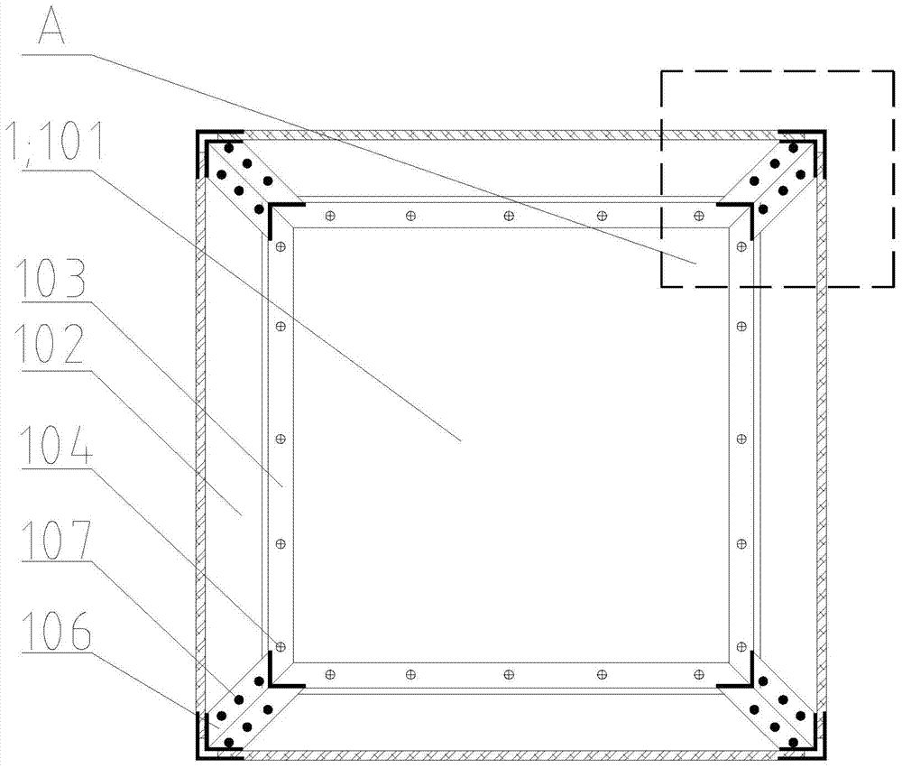
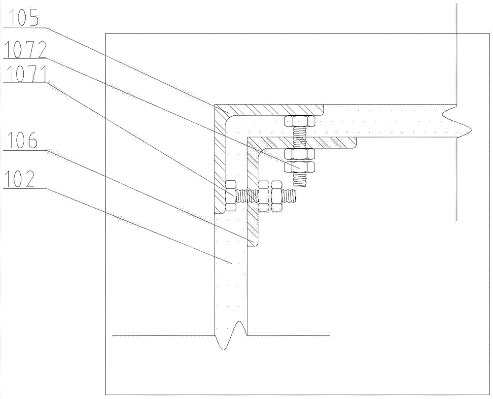
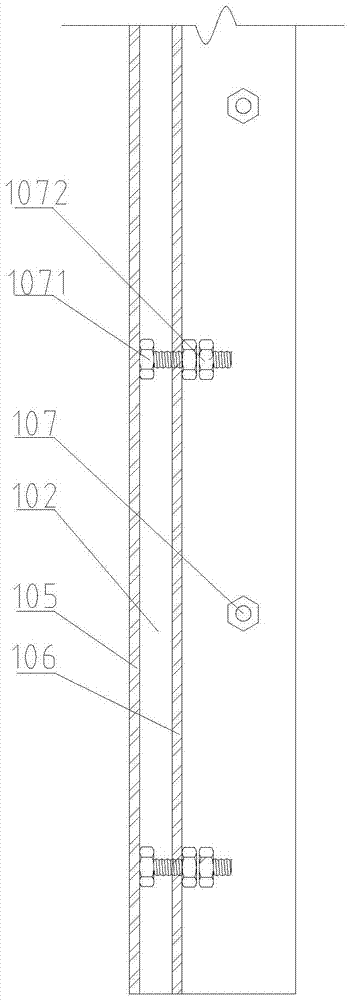
[0043] The invention discloses a combined split formwork, see Figure 1-Figure 3 , the split formwork 1 has an inverted conical structure with an open upper end as a whole, the split formwork 1 includes a bottom mold 101 and a side mold 102, the bottom mold 101 is placed horizontally, and the side mold 102 is assembled by a detachable inner liner 103 Around the bottom mold 101, the inner lining plate 103 adopts 50mm*50mm*4mm galvanized angle steel, and the two right angle sides of the galvanized angle steel are fixed with the side mold 102 and the bottom mold 101 by self-tapping screws 104, and the inner lining plate 103 is made of Galvanized angle steel ensures the lateral rigidity and longitudinal rigidity of the split formwork.

[0044] Adjacent side molds 102 are connected by a split structure, figure 2 It is a schematic diagram of the dismantling structure. The dismantling structure includes an external dismantling structure 105, an internal dismantling structure 106 an...


PUM


Abstract

The invention relates to a formwork bar laying construction method, a combined type splitting formwork and a formwork quick connector. The method comprises the following construction steps that supporting racks are erected in a full hall mode; a bar paving mode is adopted for laying battens and rib beam formworks; the combined type splitting formwork is installed between rib beams in a laid mode; rib beam steel bars and top plate steel bars are bound; concrete is poured; a side formwork body and a bottom formwork body of the combined type splitting formwork are split; the beam bottom supporting racks and the rib beam formworks are disassembled. The method has the advantages that the battens and the rib beam formworks are laid in a bar mode, compared with an existing full formwork laid mode, the formwork area can be saved, the number of the adopted steel bars is reduced, and the amount of the adopted concrete is reduced; compared with an existing integral plastic formwork, formwork disassembling is finished at least 20 days earlier, the formwork circulation cycle is shortened, the formwork lease fee is saved, and the construction period is shortened greatly; the side formwork body and the bottom formwork body of the combined type splitting formwork can be disassembled fast, and rigidity of a whole supporting system is ensured after the formwork is disassembled.

Description

technical field [0001] The invention relates to a formwork construction method, in particular to a formwork strip paving construction method, a combined detachable formwork and a formwork quick-release joint. Background technique [0002] In recent years, with the rapid development of my country's economy, the acceleration of urbanization and the development of construction technology, multi-storey buildings with brick-concrete structures in cities have gradually been replaced by long-span high-rise buildings. If the old construction technology is still used, the floor slab will be heavy, the amount of concrete and steel will be large, and the cost will be uneconomical. The emergence of the cast-in-place dense ribbed floor system will solve the characteristics of heavy self-weight and high cost. The densely ribbed floor is a high-order hyperstatically indeterminate structure, forming a space truss structure with good force and seismic performance. The densely ribbed structur...

Claims


Application Information

Patent Timeline
Patent Type & Authority Patents(China)
IPC IPC(8): E04G11/48E04G11/46E04G17/00
CPCE04G11/46E04G11/483E04G17/001
Inventor 孔祥贇贾杨刘洪伟陈雪杨帅何延龙姚久义王晓琴况成强
Owner 中青建安建设集团有限公司
Learn More