A Well Pattern and Method for Improving Fire Flooding Effect of Thick Heavy Oil Reservoir
A technology for heavy oil reservoirs and oil wells, which is applied in the field of well patterns for improving the fire flooding effect of thick heavy oil reservoirs, and can solve the problems of two-well row interference, serious oil wall damage, and unreasonable injection-production layer design. , to solve the serious gas channeling and improve the effect of fire drive
- Summary
- Abstract
- Description
- Claims
- Application Information
AI Technical Summary
Problems solved by technology
Method used
Image
Examples
Embodiment 1
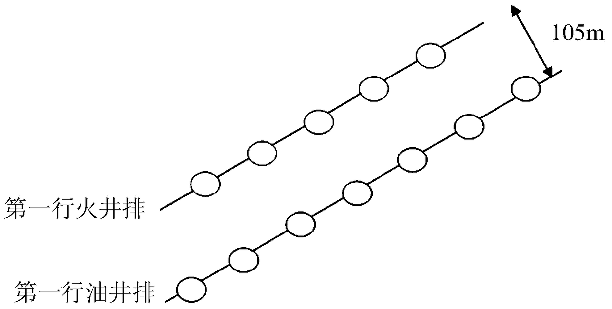
[0059] This embodiment provides a well pattern for improving the fire flooding effect of thick heavy oil reservoirs. The structure layout of the well pattern is as follows figure 2 Shown.
[0060] In the above-mentioned well pattern, a row of fire wells are linearly deployed on the top of the monoclinic structure at block 3,618. There are 6 fire wells in the fire wells, and the horizontal well spacing between two adjacent fire wells is 75m (or 50m). ;
[0061] In the downward inclination direction of the first row of fire well rows, a row of oil well rows (7 oil wells) parallel to it is deployed; the plane row distance between the oil well row and the fire well row is 105m, and there are two adjacent oil wells in the oil well row. The plane well distance between is 75-105m;
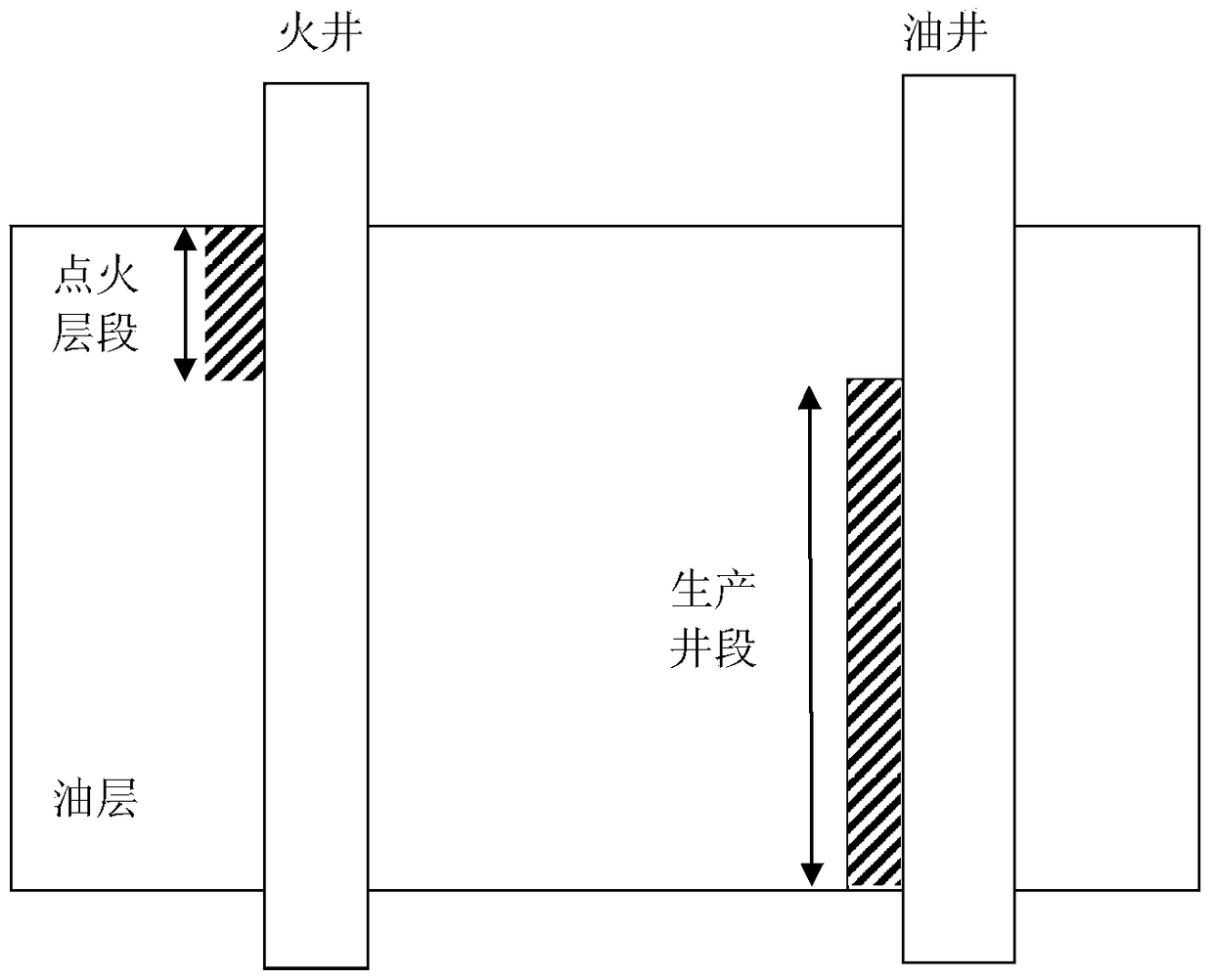
[0062] The ignition zone in the fire well is the area down the top of the oil layer. The thickness of this area accounts for 1 / 4 of the thickness of the entire oil layer (such as image 3 Shown);
[0063] The p...
Embodiment 2
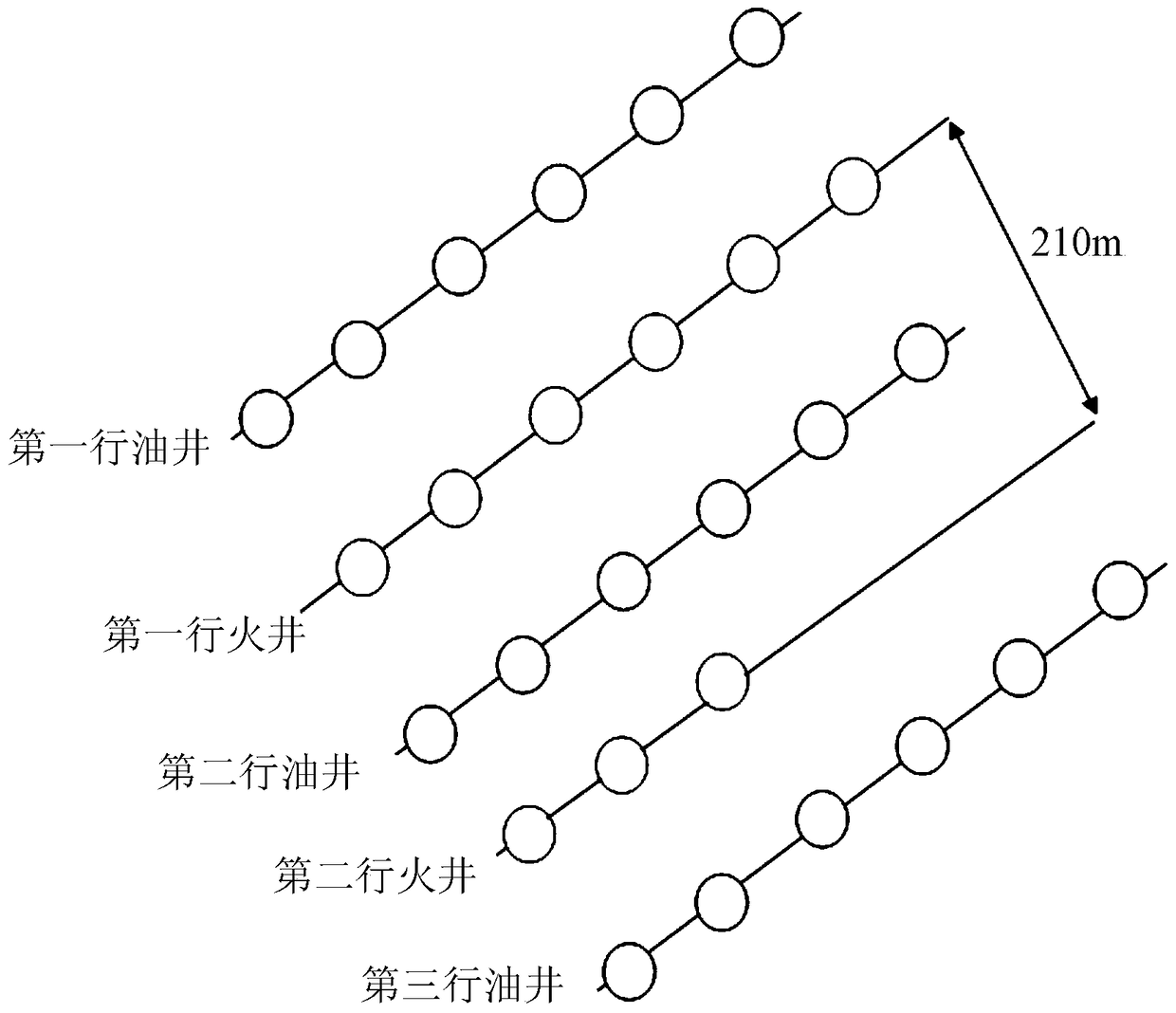
[0065] This embodiment provides a well pattern for improving the fire flooding effect of thick heavy oil reservoirs. The well pattern (such as Figure 4 (Shown) is obtained after rectification of the well pattern provided in the above comparative example 1.
[0066] 1) Shut in or plug the first row of oil wells located in the updip direction of the first row of fire well rows (to suppress gas production in the updip direction);
[0067] 2) Stop gas injection for the second row of fire wells located in the downward dipping direction of the first row (to prevent it from interfering with the fire discharge effect of the first row of fire wells in the upward dipping direction);
[0068] After such adjustments Figure 4 As shown, there is only one row of fire well rows in the well pattern, which is located in the high part of the monoclinic structure. The downward dip direction of the above fire well rows is two rows of oil well rows (labeled as the first row of oil well rows and the sec...
Embodiment 3
[0070] This embodiment provides a method for improving the fire flooding effect of thick heavy oil reservoirs. The method is carried out by using the well pattern provided in the above embodiment 1, which includes the following steps:
[0071] 1) In order to ensure that the fire drive is carried out in the high-temperature combustion mode with high displacement efficiency, it is necessary to ensure that the front of the fire drive maintains the advancing speed under high temperature combustion. The speed is taken as 8cm / d on site; The advancing speed of the edge estimates the reasonable gas injection speed of the fire well. In this example, a long tube experiment was carried out on the Gaosheng Oilfield, and the results showed that the combustion of 1m 3 Oil layer needs 300m 3 Air; according to this result, we set burning 1m 3 Oil layer needs 300m 3 For air, the advancing speed of the combustion front is 8cm / d, the thickness of the fuel oil layer is 20m, and the combustion sweep ra...
PUM
 Abstract
Description
Claims
Application Information
 - R&D
- Intellectual Property
- Life Sciences
- Materials
- Tech Scout
- Unparalleled Data Quality
- Higher Quality Content
- 60% Fewer Hallucinations
Browse by: Latest US Patents, China's latest patents, Technical Efficacy Thesaurus, Application Domain, Technology Topic, Popular Technical Reports.
© 2025 PatSnap. All rights reserved.Legal|Privacy policy|Modern Slavery Act Transparency Statement|Sitemap|About US| Contact US: help@patsnap.com


