
Well head sampling method of oil and gas well

A technology for oil and gas wells and sampling devices, applied in wellbore/well components, earth-moving drilling, etc., can solve the problems of unconsidered, unrepresentative, large difference, etc., and achieve the effect of reducing operating costs and saving operating time

Active Publication Date: 2016-05-04
CHINA FRANCE BOHAI GEOSERVICES
View PDF8 Cites 3 Cited by
  • Summary
  • Abstract
  • Description
  • Claims
  • Application Information

AI Technical Summary

Problems solved by technology

The disadvantages of these two methods of sampling are as follows: the first method of sampling does not consider the influence of gravity differentiation and pipeline friction when the formation fluid flows stably in the horizontal surface pipeline, and the formation fluid appears when it flows in the surface manifold. A kind of non-uniform flow, so sampling directly in the surface manifold, the gas-oil ratio of the sample taken is quite different from the real gas-oil ratio of the downhole formation fluid, which is not representative
In the second method of sampling, gas and liquid are sampled separately. When using samples, a certain proportion of gas and liquid samples can only be artificially mixed, which is far different from the real gas-oil ratio of the downhole formation fluid, so only It can be used as a sample preparation for laboratory analysis, but cannot be used for PVT analysis alone

Method used


Image

  • Well head sampling method of oil and gas well
  • Well head sampling method of oil and gas well
  • Well head sampling method of oil and gas well

Examples


Embodiment Construction

[0031] The invention will be further described in detail below with reference to the accompanying drawings, so that those skilled in the art can implement it with reference to the text of the description.

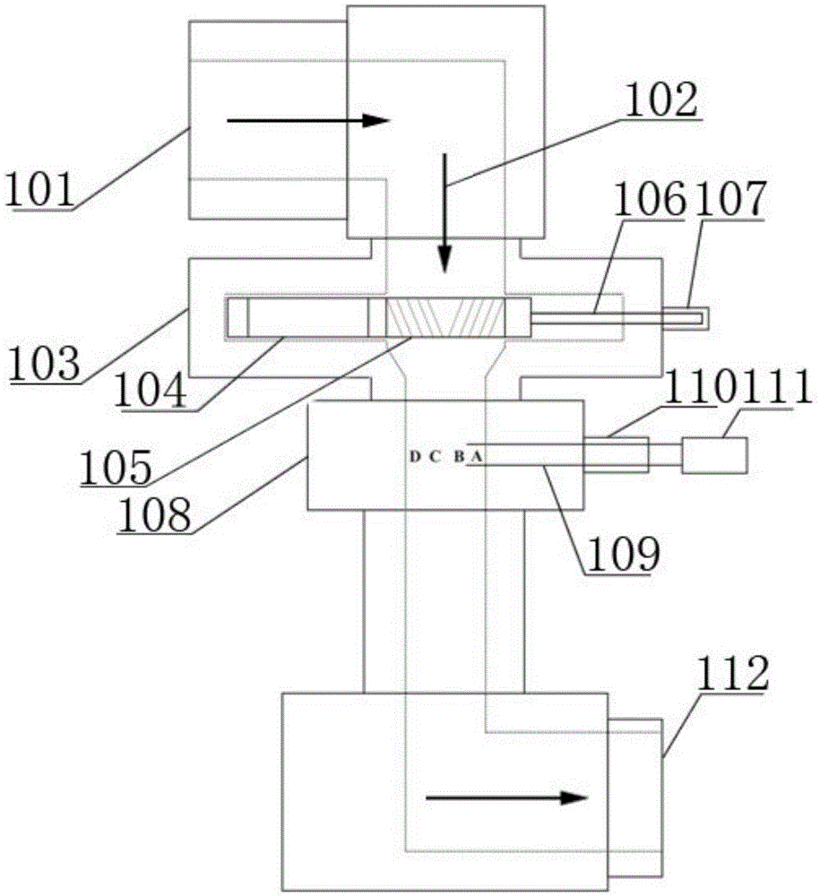
[0032] Such as figure 1 As shown, a wellhead sampling method for oil and gas wells requires the use of sampling equipment to transform the formation fluid flowing in the horizontal direction into a vertical flow through the sampling equipment, and through a filtering and mixing device in the vertical direction to realize the uneven flow of fluid More uniform distribution and flow. After uniform flow, a retractable sampling probe is used to take a certain amount of samples at different positions of the circulation channel until a special sample bottle is filled. The sampling device includes: an inlet 101, which At one end of the pipe, the other end is vertically connected with another pipe through a pipe connector to form an inlet 101. The inlet 101 pipe is fixedly connected t...


PUM


Abstract

The invention discloses a well head sampling method of an oil and gas well. The well head sampling method includes the steps that formation fluid flowing in the horizontal direction is changed into formation fluid flowing in the vertical direction through a sampling device; in the vertical direction, it is achieved that uneven-flowing fluid is changed into even distribution and flowing fluid through a filtering and mixing device; after the fluid evenly flows, a certain quantity of samples are sampled at different positions of a circulation channel through a stretchable sampling probe till a special sample bottle is full. Under the condition that the well head sampling condition meets PVT analysis of a laboratory, underground fluid samples can be completely replaced with the samples sampled with the sampling method, the sampling time is set during stable-flowing finding production, and meanwhile getting of capacity data of the oil and gas well is not influenced; compared with an underground fluid sampling method, according to the well head sampling method, the operation time is not additionally occupied, a special sampling tool is not required, the operation time of a whole well is saved, and operation cost is reduced.

Description

Technical field [0001] The invention relates to a sampling method, in particular to a wellhead sampling method for oil and gas wells. Background technique [0002] The physical parameters of formation fluids are very important parameters for evaluating the reserves of oil and gas reservoirs. The parameters are obtained by PVT analysis of formation fluid samples in the laboratory. Therefore, the quality of the samples used in PVT analysis directly determines the correctness of the oil and gas reservoir evaluation. [0003] Now there are relatively mature downhole fluid sampling methods and sampling techniques. When using downhole fluid sampling, a special sampling tool needs to be run into the well, and it takes a certain amount of operating time. Other operations cannot be performed during the sampling period. Downhole fluid sampling is expensive. The existing wellhead sampling methods are also relatively mature, but the purpose of sampling is not for laboratory PVT analysis, so i...

Claims


Application Information

Patent Timeline
Patent Type & Authority Applications(China)
IPC IPC(8): E21B49/08
CPCE21B49/086
Inventor 李纪智孙恒君王建勇林炳南毛敏房立文田立强杨毅
Owner CHINA FRANCE BOHAI GEOSERVICES
Learn More