
Signal detection device for energy distribution network fault recovery

A distribution network fault and signal detection technology, which is applied in the direction of measuring devices, fault locations, and measuring device casings, can solve problems such as poor reception of signals, slow progress of other personnel, and poor viewing of signal sources, etc., to achieve enhanced Performance, time reduction, safe and convenient use

Pending Publication Date: 2021-09-24
NORTH CHINA ELECTRIC POWER UNIV (BAODING)
View PDF0 Cites 0 Cited by
  • Summary
  • Abstract
  • Description
  • Claims
  • Application Information

AI Technical Summary

Problems solved by technology

[0004] The purpose of the present invention is to overcome the existing signal detection devices in the prior art. Some signal detection devices do not receive signals very well and the signal source is not well viewed. If the received signal is not good, it may affect the work and slow down others. The progress of personnel, the problem of wasting unnecessary time, provide a signal detection device for energy distribution network fault recovery, the signal detection device for energy distribution network fault recovery has the performance of strengthening the signal detection device, avoiding staff During detection, because the signal source of the signal detection device is weak, the progress of other people is caused, and it can also be detected in a wireless way, which reduces a lot of time and does not affect the effect of other workers' time

Method used


Image

  • Signal detection device for energy distribution network fault recovery
  • Signal detection device for energy distribution network fault recovery
  • Signal detection device for energy distribution network fault recovery

Examples


Embodiment Construction

[0023] Specific embodiments of the present invention will be described in detail below in conjunction with the accompanying drawings. It should be understood that the specific embodiments described here are only used to illustrate and explain the present invention, and are not intended to limit the present invention.

[0024] In the description of the present invention, it should be noted that the terms "upper", "lower", "inner", "outer", "front end", "rear end", "both ends", "one end", "another end" ” and other indicated orientations or positional relationships are based on the orientations or positional relationships shown in the accompanying drawings, which are only for the convenience of describing the present invention and simplifying the description, rather than indicating or implying that the referred device or element must have a specific orientation, with a specific configuration and operation, and therefore should not be construed as limiting the invention. In addit...


PUM


Abstract

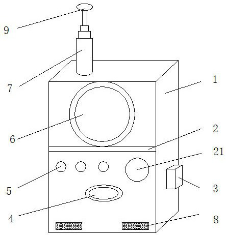
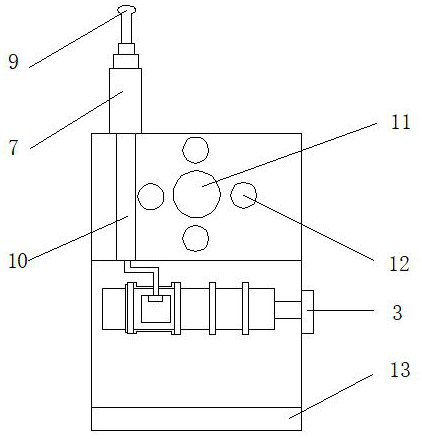
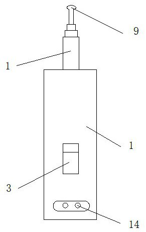
The invention discloses a signal detection device for energy distribution network fault recovery. The device comprises a shell, the surface of the shell is fixedly connected with a display screen, a partition plate is arranged below the display screen, the partition plate is fixedly connected with the surface of the shell, the lower part of the partition plate is fixedly connected with a brightness display lamp, an alarm indicator lamp is fixedly connected with one side of the brightness display lamp, a button is fixedly connected with the lower portion of the brightness display lamp, the button is connected with the brightness display lamp through an electric wire, and a signal column is fixedly connected with the interior of the shell. According to the invention, a signal strengthening module and a radio module are arranged, the performance of the signal detection device can be effectively enhanced, the situation that the progress of other workers is delayed due to the fact that a signal source of the signal detection device is weak during detection of workers is avoided, detection can be conducted in a wireless mode, a large amount of time is shortened, and the time of other workers is not affected.

Description

technical field [0001] The invention belongs to the technical field of signal detection devices, and in particular relates to a signal detection device for energy distribution network fault recovery. Background technique [0002] The detection device is mainly used in closed-loop and semi-closed-loop systems. The detection device detects the actual displacement of the actuator through direct or indirect measurement, and then feeds back to the numerical control device and compares it with the command displacement. If there is a difference, it will issue a motion control Signal, control the moving parts of the CNC machine tool to move in the direction to eliminate the difference, continuously compare the command signal and the feedback signal, and then control until the difference is 0, and the movement stops. [0003] Among the existing signal detection devices, some signal detection devices do not receive signals very well and the signal source is not viewed well. Poor rec...

Claims


Application Information

Patent Timeline
Patent Type & Authority Applications(China)
IPC IPC(8): G01R31/08G01R1/04G08C17/02
CPCG01R31/086G01R1/0408G08C17/02
Inventor 徐岩刘华夏
Owner NORTH CHINA ELECTRIC POWER UNIV (BAODING)
Learn More