Check patentability & draft patents in minutes with Patsnap Eureka AI!

Lattice-type blades of an axial-flow turbocompressor

An axial-flow turbine and blade technology, which is applied to the supporting elements of turbines, blades, and components of pumping devices for elastic fluids, etc., can solve the problems of blade imbalance, damage, and weight change, and achieve uniform support, The effect of preventing chemical attack and preventing vibration

Active Publication Date: 2018-10-12
SAFRAN AERO BOOSTERS SA
View PDF7 Cites 0 Cited by
  • Summary
  • Abstract
  • Description
  • Claims
  • Application Information

AI Technical Summary

Problems solved by technology

During operation, the openings expose the chamber to the vane environment, damaging it and making it heavy, creating an imbalance on the rotor provided with these vanes

Method used


Image

  • Lattice-type blades of an axial-flow turbocompressor
  • Lattice-type blades of an axial-flow turbocompressor
  • Lattice-type blades of an axial-flow turbocompressor

Examples


Embodiment Construction

[0046] In the following description, the terms inner and inner and outer or extrinsic indicate a position relative to the axis of rotation of the axial turbine.

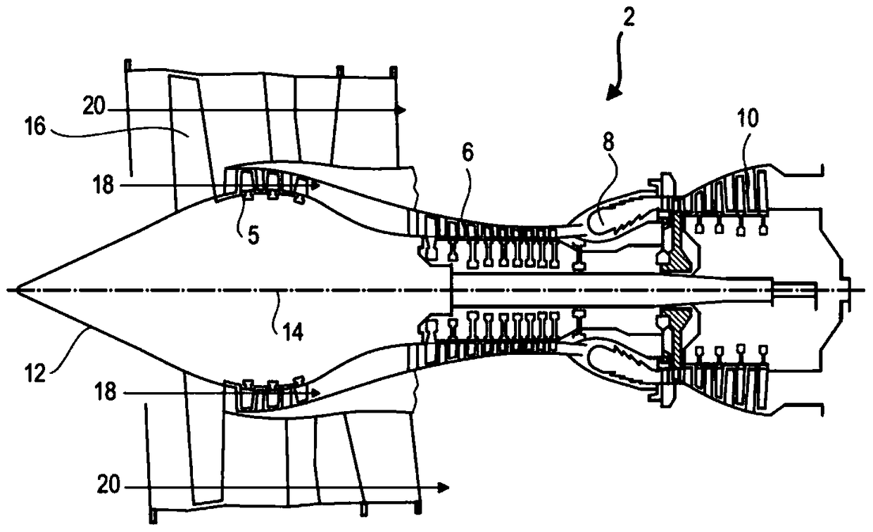
[0047] figure 1An axial turbine is shown in a simplified manner. In this particular example, it is a twin-flow turbojet. Jet engine 2 includes a first compression level referred to as low pressure compressor 5 , a second compression level referred to as high pressure compressor 6 , a combustion chamber 8 , and one or more turbine levels 10 . In operation, the mechanical power of the turbine 10 transmitted via the central shaft up to the rotor 12 operates the two compressors 5 and 6 . They comprise several rows of rotor blades associated with stator blade rows. Thus, the rotation of the rotor about its axis of rotation 14 causes an air flow to be generated and gradually compressed until introduced into the combustion chamber 8 . A step down device can increase the rotational speed delivered to the compressor.

[...


PUM

PropertyMeasurementUnit
densityaaaaaaaaaa
surface roughnessaaaaaaaaaa

Abstract

The invention relates to a blade (24) of a low-pressure compressor (5) of an axial turbomachine. The blade (24) includes a vane (30) with a cavity (42) formed therein. A bucket (30) has a leading edge (32) and a trailing edge (34), inner and outer arc surfaces extending from the leading edge (32) and the trailing edge (34), forming the inner and outer arc surfaces and defining a cavity (42) outer housing (52). The blade (24) also includes a closed foam (54), such as polymethylacrylic foam, which blocks the cavity (42) from the environment of the blade (24). The blade (24) also includes a three-dimensional lattice (48) formed in the cavity (42) and integral with the vanes (30) of the blade (24). This barrier shields against chemical attack and the introduction of impurities. The invention also relates to a production method for a hollow turbine blade filled with foam (54).

Description

technical field [0001] The field of the invention is turbomachines, in particular turbojets for aircraft. More specifically, the present invention relates to axial flow turbine blades having a reinforced lattice internal structure. Background technique [0002] The compressor and turbine of an axial turbine each include several annular rows of blades. They allow the circular airflow to be accelerated, slowed down, straightened, and even redirected. These functions allow streams to be compressed or drive energy to be recovered. To fulfill these tasks in aeronautics, the blades must be lightweight, reducing the mass of the turbine. The weight reduction also equates to a reduction in inertia with the rotor. [0003] However, the optimization of blade quality must meet the criteria of mechanical strength and thermal resistance. The blades must withstand vibrations and, where possible, the ingress of foreign objects. Furthermore, the rotor blades are subjected to centrifuga...

Claims


Application Information

Patent Timeline
Patent Type & Authority Patents(China)
IPC IPC(8): F01D5/14F01D5/16F01D5/28F01D9/02F01D25/06F04D29/02F04D29/30F04D29/42B22F7/08B22F7/00B22F5/04B22F3/105B29C45/14
CPCB22F5/04F01D5/147F05D2300/612B22F7/004B22F7/08Y02P10/25Y02T50/60B22F10/20F01D9/02F01D25/06F01D25/005F04D29/30F04D29/023B22F7/006
Inventor J-F.科特奎斯
Owner SAFRAN AERO BOOSTERS SA
Features
  • R&D
  • Intellectual Property
  • Life Sciences
  • Materials
  • Tech Scout
  • Unparalleled Data Quality
  • Higher Quality Content
  • 60% Fewer Hallucinations
Learn More