Casing type water-cooling cooler of automobile engine

A car engine, water-cooled cooling technology, applied in the direction of engine cooling, engine components, machines/engines, etc., can solve the problems of many pollutants and high fuel consumption

Inactive Publication Date: 2016-05-04
李陶胜
View PDF9 Cites 0 Cited by
  • Summary
  • Abstract
  • Description
  • Claims
  • Application Information

AI Technical Summary

Problems solved by technology

Because the engine emits more pollutants when idling, the fuel consumption is also high

Method used


Image

  • Casing type water-cooling cooler of automobile engine
  • Casing type water-cooling cooler of automobile engine

Examples


Embodiment Construction

[0008] A special tool for engine valve disassembly and assembly of the present invention will be further described in detail below in conjunction with the accompanying drawings;

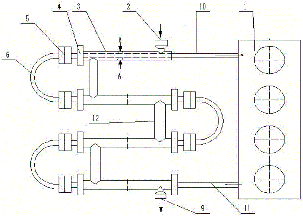
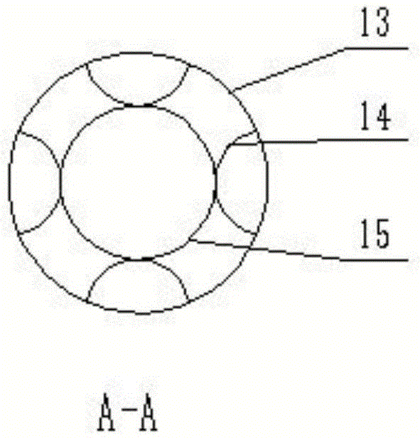
[0009] Depend on figure 1 Visible, this implementation is a kind of automobile engine casing type water-cooled cooler of the present invention: mainly by engine water jacket (1), air casing inlet (2), air casing (3,13), air casing sealing end ( 4), water pipe joint (5), water pipe elbow (6), air sleeve outlet (9), water pipe outlet (10), water pipe inlet (11), air sleeve transition pipe (12), air sleeve inner bracket ( 14), water pipe (15) constitutes.

[0010] Depend on figure 1 It can be seen that the casing-type water-cooled cooler for an automobile engine is characterized in that: the flow direction of the compressed air loaded on the periphery of the water pipe is just opposite to the flow direction of the water in the water pipe, which is beneficial to the loss of engine heat.

[0011] Depen...


PUM


Abstract

A casing type water-cooling cooler of an automobile engine mainly comprises an engine water jacket (1), an air casing inlet (2), air casings (3 and 13), air casing seal ends (4), water pipe connectors (5), water pipe elbows (6), an air casing outlet (9), a water pipe outlet (10), a water pipe inlet (11), an air casing transition pipe (12), air casing inner semi-circular supports (14) and a water pipe (15). The casing type water-cooling cooler of the automobile engine is characterized in that the flow direction of compressed air loaded to the periphery of the water pipe is opposite to the flow direction of water in the water pipe, and heat dissipation of the engine is facilitated; structures of the semi-circular supports (14) are adopted in the air casings (3 and 13), and the semi-circular supports have the function of supporting and fixing the water pipe (15).

Description

Technical field: [0001] The invention belongs to a component of an automobile engine cooling system, and in particular relates to an automobile engine sleeve type water-cooled cooler. Background technique: [0002] As the engine adopts a more compact design and has a larger specific power, the waste heat density generated by the engine also increases significantly. Some critical areas, such as around the exhaust valves, are priority areas where even a small failure of the cooling system can have catastrophic consequences. The heat dissipation capacity of the engine cooling system should generally meet the heat dissipation requirements of the engine at full load, because the heat generated by the engine is the largest at this time. However, at part load, the cooling system suffers a power loss and the water pump provides more coolant flow than required. We want the engine cold start time to be as short as possible. Because the engine emits more pollutants when idling, the ...

Claims


Application Information

Patent Timeline
Patent Type & Authority Applications(China)
IPC IPC(8): F01P9/04F01P11/04
CPCF01P9/04F01P11/04
Inventor 李陶胜金明高光辉
Owner 李陶胜
Why Eureka
Try Eureka