Compressor for an axial turbine engine with double counter-rotating rotors

A technology for turbine engines and compressors, which is applied to non-variable-capacity engines, engine components, components of pumping devices for elastic fluids, etc., can solve problems such as reduced compression rate and complexity, and achieve the effect of improving efficiency

Active Publication Date: 2019-04-16
SAFRAN AERO BOOSTERS SA
View PDF10 Cites 0 Cited by
  • Summary
  • Abstract
  • Description
  • Claims
  • Application Information

AI Technical Summary

Problems solved by technology

However, this scheme is complicated due to the number of constituent elements
Production and maintenance costs require considerable resources
Also, the compression ratio remains reduced

Method used


Image

  • Compressor for an axial turbine engine with double counter-rotating rotors
  • Compressor for an axial turbine engine with double counter-rotating rotors
  • Compressor for an axial turbine engine with double counter-rotating rotors

Examples


Embodiment Construction

[0044] In the following, the terms "inner" or "inner" and "outer" or "outer" refer to a position relative to the axis of rotation of the axial turbine engine.

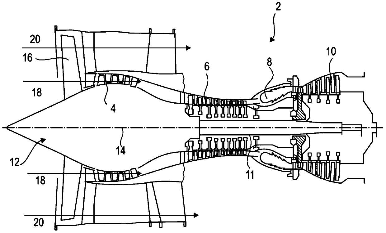
[0045] figure 1 Represents a simplified form of an axial turbine engine. In this case it is a ducted fan turbojet. The turbojet 2 comprises a first level of compression known as a low-pressure compressor 4 , a second level of compression known as a high-pressure compressor 6 , a combustion chamber 8 and one or more levels of turbines 10 . In operation, the mechanical power of the turbine 10 transmitted via the transmission shaft 11 to the rotor 12 causes the two compressors 4 to operate. The latter comprises rows of rotor blades associated with rows of stator blades. Thus, the rotation of the rotor about its axis of rotation 14 allows an airflow to be generated and progressively compressed up to the inlet of the combustion chamber 8 . A multiplier increases the rotational speed delivered to the compressor.

[0046...


PUM


Abstract

A compressor of an axial turbine engine comprising two rotors or contra-rotating drums, of which an inner rotor and an outer rotor are each provided with blade rows forming a regular alternating pattern. The inner rotor is provided with a radial annular junction fixed to the transmission shaft coming from a turbine. The outer rotor surrounds the inner rotor. The compressor also comprises a rotating bearing linked to the outer rotor and arranged axially level with the radial junction of the inner rotor so as to align the mechanical links axially. This alignment limits the effect of centrifugal force between the clearances between the blades and the walls of the rotors. A transmission with a pinion with a radial rotation axis allows the outer rotor to be driven by the inner rotor.

Description

technical field [0001] The field of the invention is turbine engines, in particular ducted fan turbojet aircraft for aviation applications. More precisely, the invention relates to the subject matter of a compressor for an axial turbine engine, in which the rotor is formed by two counter-rotating bladed parts. Background technique [0002] The use of counter-rotating rotors for compressors allows increasing the compression ratio and predetermined number of blade rows for a given length. This solution thus allows a shortening of the compressor and of the turbine engine containing the compressor, also achieving a substantial weight reduction. [0003] Document US20140286749 A1 discloses an axial turbine engine with a compressor formed by two counter-rotating rotors. Each rotor carries multiple rows of blades, the blades of the inner rotor alternating with the blades of the outer rotor. The inner rotor drives the outer rotor via a pinion, the axis of rotation of which is in ...

Claims


Application Information

Patent Timeline
Patent Type & Authority Patents(China)
IPC IPC(8): F04D19/00F04D29/056F04D29/32F02K3/072
CPCF01D1/26F01D5/03F01D25/162F02C3/067F04D19/024F04D29/059F05D2240/54F05D2240/60F05D2260/40311F01D25/24F01D15/12F04D29/324F05D2220/30
Inventor C.克拉科
Owner SAFRAN AERO BOOSTERS SA
Why Eureka
Try Eureka