A collimated light generating device based on LED light source

A technology of LED light source and generating device, which is applied in the direction of light source, lighting device, and components of lighting device, etc., can solve the problems of low light intensity, scattered light, poor light collimation and uniformity, etc., to improve efficiency and brightness 、High collimation of light output, improve the effect of lighting distance

Active Publication Date: 2018-11-30
MAANSHAN JINGZHI TECH CO LTD
View PDF6 Cites 0 Cited by
  • Summary
  • Abstract
  • Description
  • Claims
  • Application Information

AI Technical Summary

Problems solved by technology

[0005] However, the collimation device designed in this patent only pays attention to the sudden cut-off characteristics of the parabola for the LED light. Although a single LED light source can be collimated, the light intensity at the upper edge of the obtained light spot is relatively high and neat, but the light intensity at the lower edge is relatively high. Low and scattered, so the collimation and uniformity of the light obtained after collimation are not good, and cannot meet the high collimation and high uniformity requirements of some special lighting equipment or backlight
At the same time, the patent only focuses on the one-dimensional light collimation, and the light in the two-dimensional direction does not get a good collimation effect

Method used


Image

  • A collimated light generating device based on LED light source
  • A collimated light generating device based on LED light source
  • A collimated light generating device based on LED light source

Examples


Embodiment 1

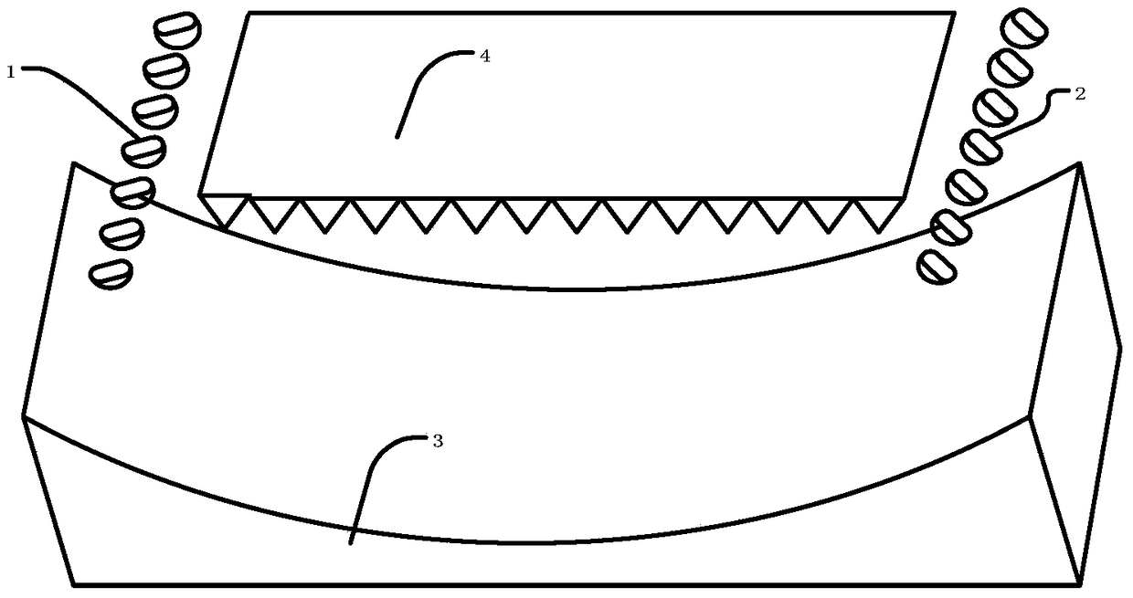
[0026] Embodiment one: if Figure 3 ~ Figure 8 As shown, a collimated light generating device based on an LED light source includes a light emitting device and a reflection device 3, and a light deflection and collimation device 4 is provided on the light output direction of the reflection device 3, and the light deflection and collimation device 4 includes a cuboid base 42 and a plurality of triangular prisms 41 arranged side by side on the cuboid base 42, the cuboid base 42 and the triangular prism 41 are optically integrated structures, the cross section of the triangular prism 41 is triangular, and the variation range of each interior angle of the triangle is 30 ° to 120 °, and the triangular prism is This triangle is stretched and formed, and the surface of the triangular prism 41 is used as the incident surface of the light deflection and collimation device 4 towards the reflection device 3, and the surface of the cuboid base 42 is used as the light exit surface of the li...

Embodiment 2

[0029] Embodiment two: if Figure 9 ~ Figure 11 As shown, other structures are the same as in Embodiment 1, except that a one-dimensional lens array 5 is arranged between the light emitting array 1 and the paraboloid 31, a one-dimensional lens array 6 is arranged between the light emitting array 2 and the paraboloid 32, and a one-dimensional lens array 5 is arranged between the light emitting array 2 and the paraboloid 32. The sum 6 is composed of a plurality of arcuate lenses 52 arranged side by side on the base 51 , and the arrangement direction of the arcuate lenses 52 is consistent with the extending direction of the triangular prism 41 .

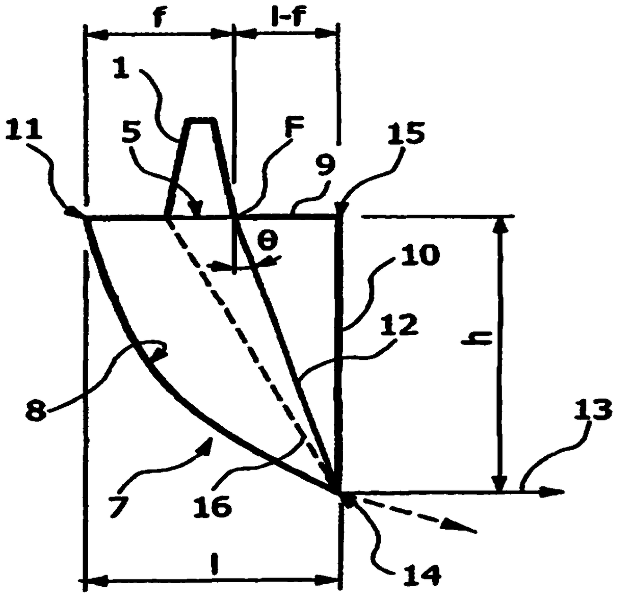
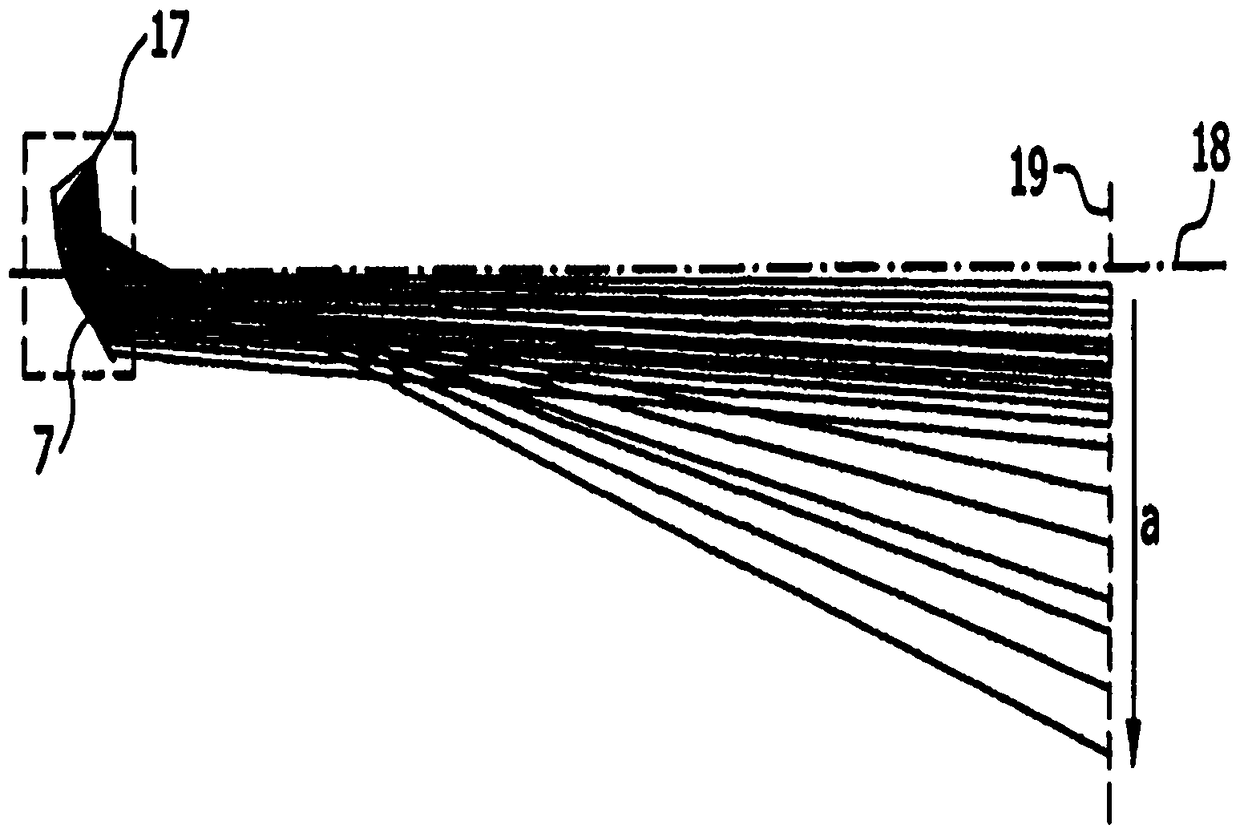
[0030] like Figure 11, before adding the one-dimensional lens array, the rays 01 and 02 on both sides of the center line 11 of an LED light source are irradiated on the parabolic reflective surface 3, and reflection occurs. After the reflection, the rays 01 and 02 are not collimated, and at a certain angle The incident light is incide...

Embodiment 3

[0031] Embodiment three: as Figure 12 As shown, the other structures are the same as those in Embodiment 1 or 2, except that the parabolic reflector 3 is two symmetrical annular paraboloids extending circularly around the central vertical line at the intersection of the two parabolas, and the focal points of all parabolas connect the line These are two semi-circular lines, and the light emitting devices are two LED light sources 1 and 2 symmetrically arranged on the said line of focus.


PUM


Abstract

The invention discloses a collimated light generating device based on an LED light source. The collimated light generating device comprises a light-emitting device and a reflection device and is characterized in that the reflection device is provided with a parabola-shaped reflecting surface, and the light-emitting device is arranged on the focus of the parabola-shaped reflecting surface; a light ray deflection collimating device is arranged in the light-emitting direction of the reflection device and comprises a cuboid base and a plurality of triangular prisms which are arranged on the cuboid base side by side, and the cuboid base and the triangular prisms are arranged to be of an integrated optical structure; the surfaces of the triangular prisms serve as the light incident face of the light ray deflection collimating device and face the reflection device, and the surface of the cuboid base is used as the light emergent face of the light ray deflection collimating device. The collimated light generating device based on the LED light source has the advantages that light collimating can be achieved quite efficiently, and a complete light spot is formed.

Description

technical field [0001] The invention relates to an optical collimation device, in particular to a collimated light generating device based on an LED light source. Background technique [0002] LED itself has the advantages of low power consumption, high brightness, waterproof and shockproof, etc., and with the rapid development of the LED industry and breakthroughs in technology, the application prospect of LED is becoming more and more broad, and has penetrated into all aspects of life from lighting to display. . Therefore, the requirements for the collimation and efficiency of LED light sources are also getting higher and higher. For example, LED light sources with high collimation are required in the field of LED backlighting. At the same time, in some special lighting, such as diving lamps, etc., high-collimation and high-efficiency LED light sources are also required. However, due to the limitations of the shape and technology of the LED itself, high-efficiency colli...

Claims


Application Information

Patent Timeline
Patent Type & Authority Patents(China)
IPC IPC(8): F21V13/04F21Y115/10
CPCF21V13/04
Inventor 武鹏李同朱宗杰陈志明张蕊蕊
Owner MAANSHAN JINGZHI TECH CO LTD
Why Eureka
Try Eureka