Two-stage heat exchanger

A secondary heat exchanger and secondary heat exchange technology, which is applied in evaporators/condensers, lighting and heating equipment, refrigeration components, etc., can solve the problems of heat conduction and heat conduction, which can easily affect each other and reduce the heat exchange efficiency of heat exchangers. , to achieve the effect of maintaining supercooling, improving energy efficiency, and good heat exchange effect

Active Publication Date: 2016-05-04
FOSHAN GUANGTENG NEW ENERGY CO LTD
View PDF3 Cites 8 Cited by
  • Summary
  • Abstract
  • Description
  • Claims
  • Application Information

AI Technical Summary

Problems solved by technology

However, the existing secondary heat exchanger has the following disadvantages: (1) the water exchange pipe and the enthalpy heat exchange pipe of the existing air injection enthalpy heat exchanger are all arranged in its main refrigerant passage, and are connected with the main refrigerant channel at the same time. The heat exchange of the refrigerant in the refrigerant channel, the heat transfer between the heat exchange water pipe and the refrigerant, and the heat transfer between the enthalpy-increasing heat exchange pipe and the refrigerant are easy to interact, thereby reducing the heat exchange efficiency of the heat exchanger

Method used


Image

  • Two-stage heat exchanger
  • Two-stage heat exchanger
  • Two-stage heat exchanger

Examples


Embodiment 1

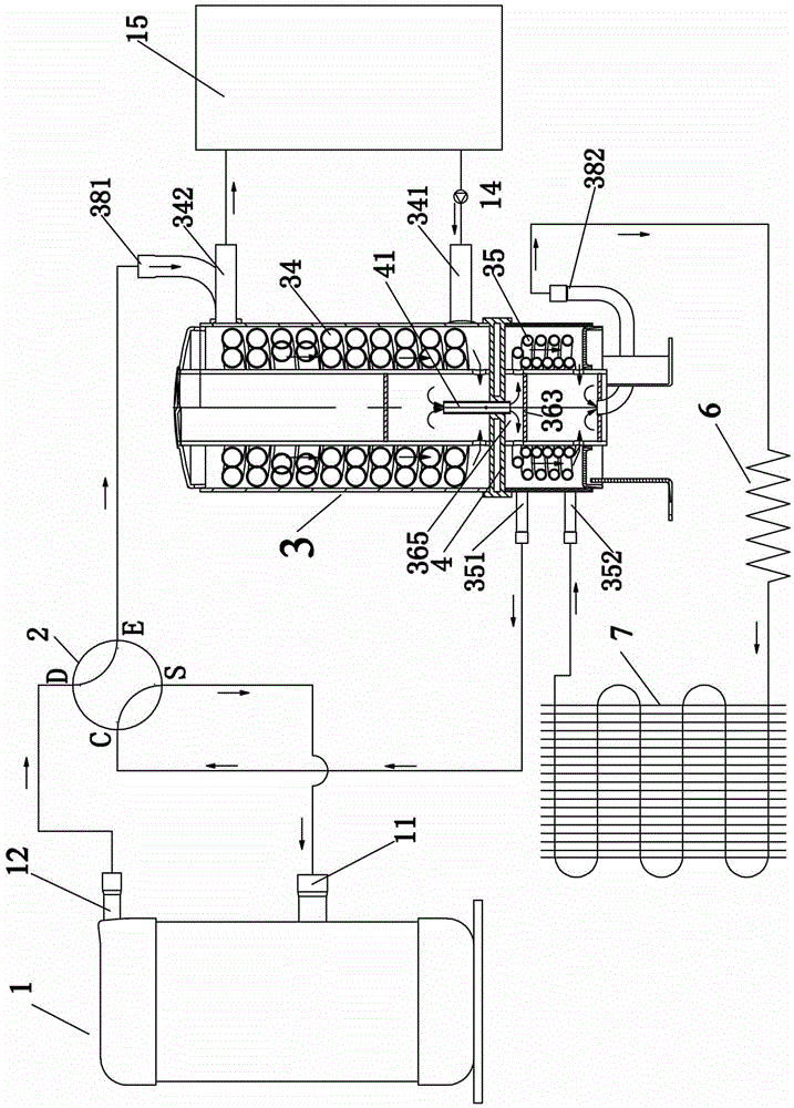
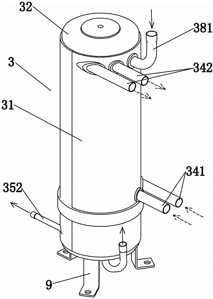
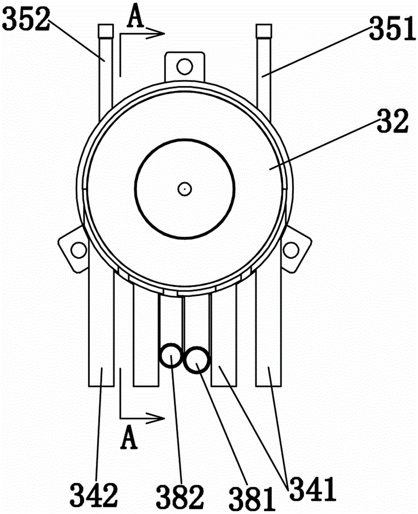
[0032] Embodiment one, such as Figure 1 to Figure 5 As shown, a heat pump water heater includes a compressor 1, a four-way valve 2, a secondary heat exchanger 3, a first throttling device 6, a second heat exchanger 7, and a water storage tank 15. The secondary heat exchanger 3 includes a housing 31, the housing 31 is divided into a primary heat exchange cavity 38 and a secondary heat exchange cavity 39 by a partition 4, and a primary heat exchange cavity 38 and a secondary heat exchange cavity 39 are respectively provided with a The first-stage heat exchange tube 34 and the second-stage heat exchange tube 35 , the partition plate 4 is provided with a communication channel 41 , and the communication channel 41 communicates with the first-stage heat exchange chamber 38 and the second-stage heat exchange chamber 39 .

[0033] The housing 31 is respectively provided with a first refrigerant inlet 381 and a first refrigerant outlet 382 corresponding to the primary heat exchange ca...


PUM


Abstract

The invention relates to a two-stage heat exchanger. According to the two-stage heat exchanger, the interior of a shell is divided into a first-stage heat exchange cavity and a second-stage heat exchange cavity through a partition plate, the first-stage heat exchange cavity communicates with the second-stage heat exchange cavity through a communicating channel on the partition plate, a first-stage heat exchange pipe is arranged in the first-stage heat exchange cavity, and a second-stage heat exchange pipe is arranged in the second-stage heat exchange cavity. When the two-stage heat exchanger is used as a condenser and the supercooling degree of the first-stage heat exchange pipe is small, the second-stage heat exchange pipe can be put into use together; firstly, superheated refrigerant steam in the first-stage heat exchange cavity rapidly exchanges heat with cooling liquid in the first-stage heat exchange pipe and then is condensed into liquid refrigerant; then, the liquid refrigerant enters the second-stage heat exchange cavity, the liquid refrigerant in the second-stage heat exchange pipe is evaporated or saturated refrigerant steam absorbs heat of the liquid refrigerant, and therefore the refrigerant in the second-stage heat exchanger can be sufficiently supercooled before throttling, the supercooling degree of a refrigerant system is kept, the pressure of the refrigerant system and loads on a compressor are reduced, and overall energy efficiency of a unit can be improved.

Description

technical field [0001] The invention relates to the technical field of heat exchangers, in particular to a secondary heat exchanger. Background technique [0002] At present, the general heat exchangers are designed in a single-stage heat exchange mode. When the temperature of the coolant rises, the subcooling degree of the system decreases, which will lead to a decrease in the heat transfer effect of the working medium, high temperature and high pressure of the working medium. , so that the performance of the entire system is greatly reduced, the power consumption is increased, and the capacity is reduced. [0003] Therefore, to solve these defects of the existing single-stage heat exchanger, a heat exchanger that can maintain the subcooling degree of the working fluid system and reduce the load of the compressor at high temperature is needed. Therefore, in response to some problems existing in the current heat exchanger, domestic heat exchanger manufacturers have develope...

Claims


Application Information

Patent Timeline
Patent Type & Authority Applications(China)
IPC IPC(8): F25B39/04
CPCF25B39/04
Inventor 冯永坚罗志锋张嘉庆
Owner FOSHAN GUANGTENG NEW ENERGY CO LTD
Why Eureka
Try Eureka