A Method of Pneumatic Separation of Bullet Holder by Muzzle Cutter

A pneumatic separation and cutter technology, which is applied in ammunition testing, ammunition, weapon accessories, etc., can solve the problems of projectile speed influence, easy mutual interference, and inability to closely cooperate with the overall seal, so as to ensure stability, ensure tight fit and Hermeticity, the effect of eliminating mutual interference

Active Publication Date: 2017-05-03
HARBIN INST OF TECH
View PDF6 Cites 0 Cited by
  • Summary
  • Abstract
  • Description
  • Claims
  • Application Information

AI Technical Summary

Problems solved by technology

[0007] In order to solve the problem that the flaps of the existing petal-shaped cracked bullet holder cannot be closely matched and integrally sealed, the stability of the accelerated movement of the bullet holder and the bullet in the chamber is affected; and when the bullet holder is separated, the flaps are easy to interfere with each other, resulting The problem of the impact of support separation on the projectile velocity provides a method for aerodynamic separation of the projectile support through the muzzle cutter

Method used


Image

  • A Method of Pneumatic Separation of Bullet Holder by Muzzle Cutter
  • A Method of Pneumatic Separation of Bullet Holder by Muzzle Cutter
  • A Method of Pneumatic Separation of Bullet Holder by Muzzle Cutter

Examples


specific Embodiment approach 1

[0019] Specific implementation mode one: combine Figure 1 to Figure 5 Illustrate this embodiment, a kind of method that realizes the aerodynamic separation of bullet holder by muzzle cutter, it comprises the following steps:

[0020] Step 1: Installation of cutter and bullet holder:

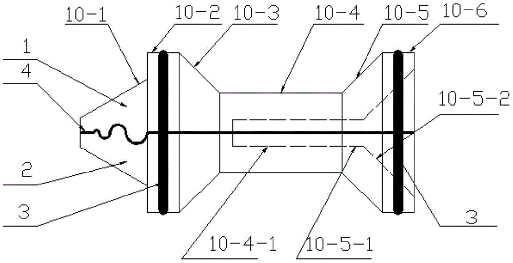
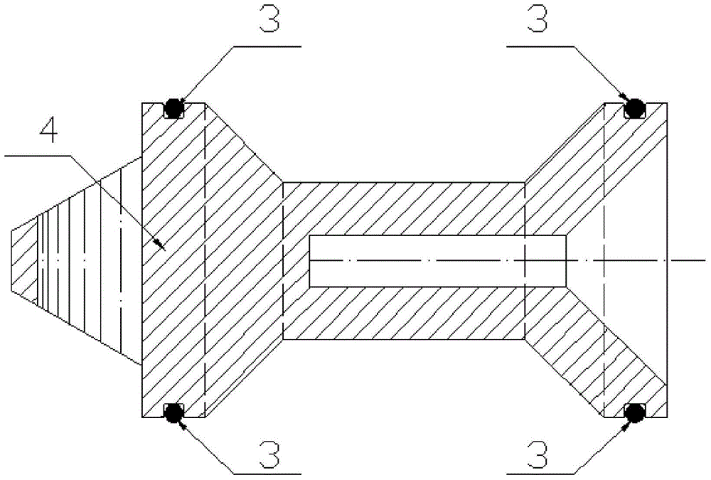
[0021] The upper lobe 1 and the lower lobe 2 are cut from the same rotator along the symmetrical plane, and multiple muzzle cutters 6 are installed on the outer surface of the gun bore in the direction of the outlet. On the right are the first tapered section 10-1, the first columnar section 10-2, the tapered section 10-3, the second columnar section 10-4, the second tapered section 10-5 and The third columnar section 10-6; the upper lobe 1 and the lower lobe 2 are matched on the first gradually expanding cone section 10-1 by means of involute arc teeth; the upper lobe 1 and the lower lobe 2 are coated with Thin-layer plastic 4; the first columnar section 10-2 and the third columnar section 10...

specific Embodiment approach 2

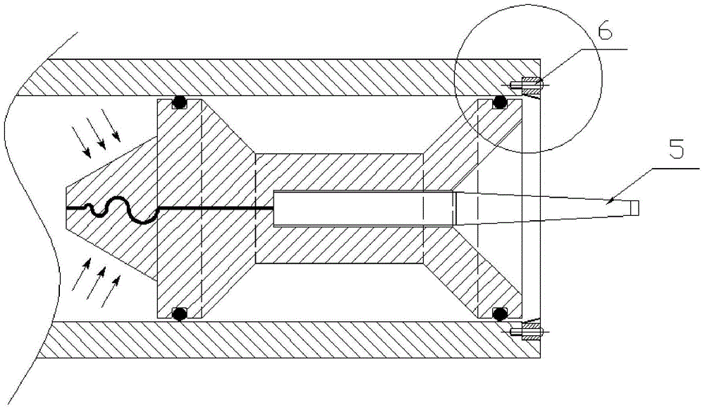
[0026] Specific implementation mode two: combination Figure 3 to Figure 5Describe this embodiment, each muzzle cutter 6 in a plurality of muzzle cutters 6 in step 1 of this embodiment all comprises cutting blade frame 6-1 and cutting blade 6-2, and cutting blade frame 6-1 Installed on the outer wall of the gun bore by bolts, the cutting blade 6-2 is installed on the lower end of the cutting tool holder 6-1, and the lower edge of the cutting blade 6-2 stretches out toward the gun bore inner cavity. When the bullet holder moves forward at high speed, the inner surface of the variable diameter reaming hole 10-5-2 is affected by high-pressure pneumatic force; the two sealing rings 3 on the bullet holder are sequentially split by the muzzle cutter 6 when the bullet is discharged from the bore, as image 3 Shown; Wherein the cutting blade 6-2 lower edge protrudes into the gun bore less than the gap between the bullet holder and the gun chamber, and the cutting blade 6-2 does not co...

specific Embodiment approach 3

[0027] Specific implementation mode three: combination Figure 3 to Figure 5 To illustrate this embodiment, the cutting blade 6-2 in Step 1 of this embodiment is a triangular cutting piece, and the cutting edge of the cutting blade 6-2 faces the cavity exit direction of the upper lobe 1 and the lower lobe 2. Such setting is convenient to ensure that the blade faces the sealing ring and cuts the sealing ring just in time. Other compositions and connections are the same as those in the second embodiment.


PUM


Abstract

The invention discloses a sabot capable of realizing pneumatic separation through muzzle cutters, and relates to a sabot. By adopting the sabot disclosed by the invention, the problems of a current segmented fractured sabot that close match and integral sealing cannot be realized among segments, so that the stability of accelerated movement of the sabot and a bullet in a bore is affected; and interference can easily occur among the segments during separation of the sabot, so that the speed of the bullet is affected by separation of the sabot are solved. According to the sabot, the upper and lower segments of the sabot are formed by cutting the same rotary body along a symmetrical surface, and the two segments are matched with each other at a tail part divergent conic section through divergent arc teeth; matched surfaces of the upper segment and the lower segment are separately coated with a thin layer of rubber; the front and rear cylindrical sections of the sabot are separately provided with an annular groove; after the upper segment is matched with the lower segment, the two annular grooves are separately provided with a sealing ring, so that the sabot can be arranged in the bore in a slidable manner; the multiple muzzle cutters are arranged on the outer surface of the bore in the outlet direction; and the sealing rings are cut when the sabot leaves the bore, so that pneumatic separation is realized after the sabot leaves the bore. The sabot disclosed by the invention is applicable to the experiment of shooting a subcaliber bullet with a light-gas gun.

Description

technical field [0001] The invention relates to a method for aerodynamically separating bullet holders, in particular to a method for pneumatically separating bullet holders in an experimental device for launching subcaliber high-speed supercavitation projectiles by using a light gas cannon. Background technique [0002] The light gas gun is a device that uses the high-pressure air chamber at the rear end of the chamber to supply air to the chamber and push the projectile to accelerate in the chamber so that it can obtain a certain speed out of the chamber. It is currently widely used in various projectile launches and projectile collisions. Damage experiment. In order to obtain a higher exit velocity for the projectile, in addition to increasing the pressure of the air chamber and the length of the chamber, it is also a convenient and effective means to expand the diameter of the chamber and use the bullet holder to adapt to launch sub-caliber projectiles. [0003] When us...

Claims


Application Information

Patent Timeline
Patent Type & Authority Patents(China)
IPC IPC(8): F42B35/00
CPCF42B35/00
Inventor 王聪仇洋王威曹伟
Owner HARBIN INST OF TECH
Why Eureka
Try Eureka