3D anisotropic micro seismic interference inverse positioning method and 3D anisotropic micro seismic interference inverse positioning system

A three-dimensional and all-directional, positioning method technology, applied in the field of geophysical exploration, can solve the problems of limitation and large amount of observation data, and achieve the effect of improving calculation speed, improving calculation efficiency, high positioning accuracy and reliability

Inactive Publication Date: 2016-05-04
INST OF GEOLOGY & GEOPHYSICS CHINESE ACAD OF SCI
View PDF2 Cites 20 Cited by
  • Summary
  • Abstract
  • Description
  • Claims
  • Application Information

AI Technical Summary

Problems solved by technology

However, this method also has its limitations. It needs to obtain clear P- and S-wave travel time information from seismic records (Flinn, 1965), and requires seismic records to have a high signal-to-noise ratio. However, in actual microseismic monitoring data, low The signal-to-noise ratio is a common feature of observation data, and the amount of observation data is huge, so the traditional Geiger-like methods are greatly limited

Method used


Image

  • 3D anisotropic micro seismic interference inverse positioning method and 3D anisotropic micro seismic interference inverse positioning system
  • 3D anisotropic micro seismic interference inverse positioning method and 3D anisotropic micro seismic interference inverse positioning system
  • 3D anisotropic micro seismic interference inverse positioning method and 3D anisotropic micro seismic interference inverse positioning system

Examples


Embodiment 2

[0064] In embodiment 2, on the basis of embodiment 1, said step 1 specifically includes the following steps:

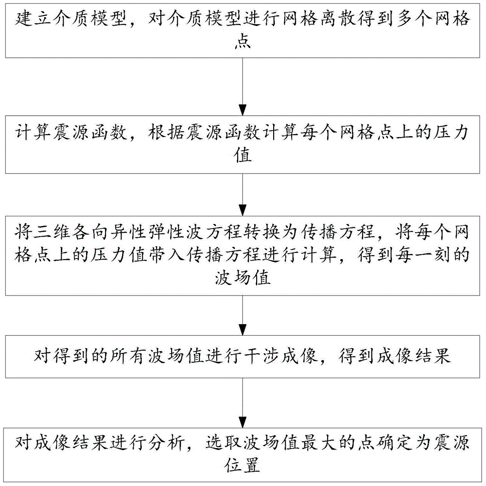
[0065] Step 1.1: Establish a medium model according to the geological background conditions, the actual measured petrophysical test data and logging data;

[0066] Step 1.2: The medium model is discretized using a regular-shaped three-dimensional grid to obtain grid points.

Embodiment 3

[0067] In embodiment 3, on the basis of embodiment 1 or 2, described source function adopts Gaussian function on space, adopts Ricker wavelet on time, and the specific formula of described source function is:

[0068] s(x,y,z,t)=g(x,y,z)·f(t) formula (1)

[0069] Among them, f(t)=(1-2(πf 0 t) 2 )exp(-(πf 0 t) 2 ) formula (2)

[0070] g ( x , y , z ) = exp { [ - ( x - x 0 ) 2 + ( z - z o ) ...

Embodiment 4

[0072] In embodiment 4, on the basis of any embodiment of embodiment 1-3, said step 3 specifically includes the following steps:

[0073] Step 3.1: Substituting the differential in the three-dimensional anisotropic elastic wave equation with a differential approximation to obtain the corresponding propagation equation in the finite difference format, and the spatial sampling step and time sampling step in the propagation equation must satisfy the stability of the numerical format sexual condition;

[0074] Step 3.2: Use the regional decomposition method to bring the pressure value on each grid point into the propagation equation for calculation, and obtain the wave field value at each moment.

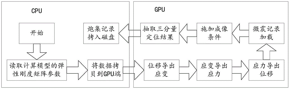
[0075] In this embodiment, further, in the step 3.2, using GPU to perform finite difference calculation on the three-dimensional anisotropic elastic wave equation at each calculation node by means of domain decomposition, the specific method for obtaining the wave field value at each mo...


PUM


Abstract

The invention relates to a 3D anisotropic micro seismic interference inverse positioning method and a 3D anisotropic micro seismic interference inverse positioning system. The method comprises the following steps: (1) building a medium model, and performing grid discretization of the medium model to get multiple grid points; (2) calculating a seismic source function, and calculating the pressure value of each grid point according to the seismic source function; (3) converting a 3D anisotropic elastic wave equation into a propagation equation, and substituting the pressure value of each grid point into the propagation equation for calculation to get the wave field value at each moment; (4) performing interference imaging of all the obtained wave field values to obtain an imaging result; and (5) analyzing the imaging result, and determining the point with the maximum wave field value as the location of the seismic source. Micro seismic positioning is carried out by use of a wave equation-based positioning method which has the advantages of high positioning accuracy and reliability and the like. By adoption of GPU acceleration 3D anisotropic micro seismic inverse positioning, the computation speed is greatly improved, and the computation efficiency is improved.

Description

technical field [0001] The invention relates to a microseismic positioning method, in particular to a three-dimensional anisotropic microseismic interference reverse time positioning method and system, belonging to the field of geophysical exploration. Background technique [0002] Traditional earthquake location work can be traced back to Geiger's work in 1910 (Geiger, 1912; BrattandBache, 1988). Later, it was further improved and formed the most common method in earthquake location---Geiger's method. The core of Geiger's method includes two parts. First, it linearizes the nonlinear relationship between the source position of the earthquake and the travel time of the seismic wave. Second, it uses the least square method to solve the linear system. , this method has been widely used. However, this method also has its limitations. It needs to obtain clear P- and S-wave travel time information from seismic records (Flinn, 1965), and requires seismic records to have a high si...

Claims


Application Information

Patent Timeline
Patent Type & Authority Applications(China)
IPC IPC(8): G01V1/00G01V1/30G01V1/28
CPCG01V1/00G01V1/282G01V1/307G01V2210/63
Inventor 薛清峰王一博常旭姚振兴
Owner INST OF GEOLOGY & GEOPHYSICS CHINESE ACAD OF SCI
Why Eureka
Try Eureka