
A laser scanning system and method based on a mobile intelligent terminal

A mobile intelligent terminal and laser technology, which is applied in the field of laser code scanning, can solve problems such as lighting, high accuracy requirements, complex hardware structure, unfavorable mobile office, etc. small effect

Active Publication Date: 2017-04-19
JIANGSU ZHILIAN TIANDI TECHNOLOGY CO LTD
View PDF1 Cites 0 Cited by
  • Summary
  • Abstract
  • Description
  • Claims
  • Application Information

AI Technical Summary

Problems solved by technology

In the prior art, the professional scanning device is as described in the barcode scanning gun published in the patent document CN104123521A, which includes a gun body and a wireless transmitting device, and the wireless transmitting device is connected to the gun body for use, and the lower end of the gun body is provided with a handle, one end of the handle is provided with a data interface, the front end of the gun body is provided with a scanning head, the scanning head is connected with a circuit board located in the gun body, the circuit board is connected with the data interface, and the data The interface socket is connected with the wireless transmitting device. Using this system is not only complicated in hardware structure, but also depends on computer equipment, which is inconvenient to carry and is not conducive to mobile office
[0003] At present, although some mobile phones provide scanning mode, they have high requirements on illumination and accuracy, which improves the environmental conditions and human control factors of use.

Method used


Image

  • A laser scanning system and method based on a mobile intelligent terminal
  • A laser scanning system and method based on a mobile intelligent terminal

Examples


Embodiment Construction

[0023] The specific embodiment of the present invention is described below:

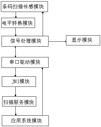
[0024] Such as figure 1 As shown, a laser scanning code system based on a mobile intelligent terminal includes a barcode scanning sensor module for converting a one-dimensional code or a two-dimensional code into a digital signal that can be recognized by a processor. The laser scanning system also includes a level Conversion module, signal processing module, serial port driver module, JNI module, scanning service module, application system module, display module, the level conversion module is used to reduce the digital signal level output by the barcode scanning sensor, and the signal processing module is used to realize the digital signal Processing and display, the serial port driver module is used to obtain the data of the hardware serial port, and provides methods for the upper layer to open the serial port device and control the startup of the scanning module. The JNI module is used to control...


PUM


Abstract

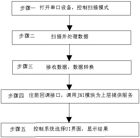
The invention discloses a laser barcode scanning system and method based on a mobile intelligent terminal, and belongs to the technical field of laser barcode scanning. The system comprises a barcode scanning sensing module, a level conversion module, a signal processing module, a serial port driving module, a JNI (Java Native Interface) module, a scanning service module, an application system module and a display module. The method comprises the following steps: 1) starting serial port equipment, and controlling a scanning mode; 2) scanning and processing data; 3) receiving the data, and carrying out data conversion; 4) registering a callback interface, and calling the JNI module to provide a service interface for an upper-layer application; and 5) controlling the system to select a UI (User Interface) display way, and displaying a result. The laser barcode scanning system and method are completely realized on the basis of the mobile intelligent terminal, scanning accuracy is improved, scanning is not restricted by environment, barcode scanning speed is quickened, and the equipment is convenient in carrying, is small and portable and is especially suitable for occasions of mobile office.

Description

technical field [0001] The invention specifically relates to a laser code scanning system and method based on a mobile intelligent terminal, and belongs to the technical field of laser code scanning. Background technique [0002] Laser scanning is a barcode recognition technology that is widely used now. Barcodes include one-dimensional codes and two-dimensional codes. In the prior art, the professional scanning device is as described in the barcode scanning gun published in the patent document CN104123521A, which includes a gun body and a wireless transmitting device, and the wireless transmitting device is connected to the gun body for use, and the lower end of the gun body is provided with a handle, one end of the handle is provided with a data interface, the front end of the gun body is provided with a scanning head, the scanning head is connected with a circuit board located in the gun body, the circuit board is connected with the data interface, and the data The inter...

Claims


Application Information

Patent Timeline
Patent Type & Authority Patents(China)
IPC IPC(8): G06K7/14
CPCG06K7/1408
Inventor 赵祖朝胡东纯钱志明赵华刘永福
Owner JIANGSU ZHILIAN TIANDI TECHNOLOGY CO LTD
Learn More