
Night lamplight image interaction radiation correction method based on stable mapping points

A technology for nighttime light image and radiation correction, applied in the direction of instruments, character and pattern recognition, computer parts, etc. The effect of accurate calibration and high calibration accuracy

Active Publication Date: 2016-05-04
INST OF REMOTE SENSING & DIGITAL EARTH CHINESE ACADEMY OF SCI
View PDF2 Cites 18 Cited by
  • Summary
  • Abstract
  • Description
  • Claims
  • Application Information

AI Technical Summary

Problems solved by technology

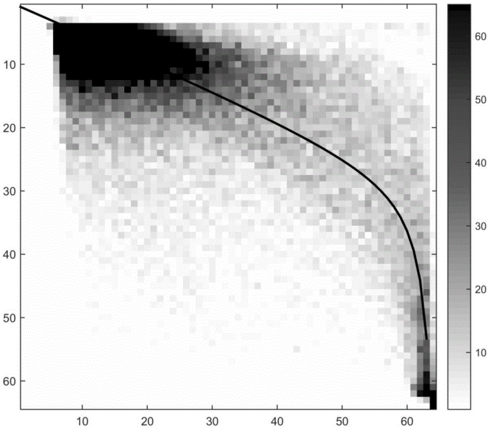
In the selection of image correction points, it has been corrected by selecting stable bright pixels on long-term images as correction points, but because the DN value of the image is only 64 levels, the DN value of the pixel in the area with large light brightness is extremely high. It is easy to be saturated, this method does not eliminate the saturation point, so the calibration point still has certain uncertainty; in addition, the constant target area method often assumes that the light brightness value of this area does not change between years, and this area has a long-term It is impossible to exist in the sequence, and it also introduces some inaccuracies in the correction points caused by the change of the actual light brightness; in the selection of the model, the quadratic polynomial is a more commonly used fitting model, but the fitting result It cannot fit all the points very well, especially the points whose DN values ​​are distributed around 0 and 63 have a certain gap in the fitting results
To sum up, there is still no accurate correction method for the problem of radiation correction between luminous remote sensing image data.

Method used


Image

  • Night lamplight image interaction radiation correction method based on stable mapping points
  • Night lamplight image interaction radiation correction method based on stable mapping points
  • Night lamplight image interaction radiation correction method based on stable mapping points

Examples


Embodiment Construction

[0037] The present invention will be described in detail below in conjunction with the accompanying drawings. However, it should be understood that the accompanying drawings are provided only for better understanding of the present invention, and they should not be construed as limiting the present invention.

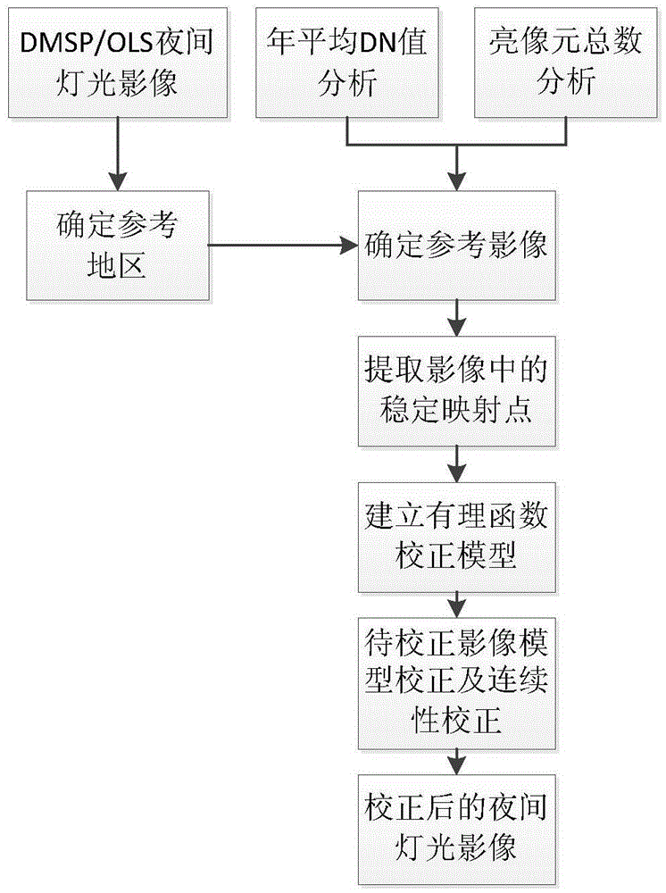
[0038] like figure 1 As shown, the mutual radiation correction method between night light images based on stable mapping points provided by the present invention includes the following steps:

[0039] 1. Read the night light image to be corrected for mutual radiation.

[0040] The present invention uses DMSP / OLS data as an example for illustration, but is not limited thereto. The DMSP / OLS data can be obtained by downloading from the website of the National Oceanic and Atmospheric Administration of the United States. DMSP / OLS data is annual raster image data, the reference system is WGS_84 coordinate system, the image acquisition width is 3000km, and the spatial resolu...


PUM


Abstract

The invention relates to a night lamplight image interaction radiation correction method based on stable mapping points. The night lamplight image interaction radiation correction method is characterized by comprising the following steps that firstly, night lamplight images to be corrected in an interaction radiation mode are read; secondly, a reference area is determined according to the read-in night lamplight images; thirdly, a correction reference image is determined; fourthly, the stable mapping points in the images are extracted to serve as regression calculating points of interaction correction mode parameters; fifthly, a rational function correction model between the DN value of the reference image in the regression calculating points and the mapping DN values of the images to be corrected is established, and correction parameters are obtained through calculation; sixthly, the correction parameters obtained in the fifth step are adopted to correct the images to be corrected. The night lamplight image interaction radiation correction method can be widely applied to interaction correction of a plurality of satellite sensors for night lamplight data acquired by business type line scanning sensors carrying night stable lamplight intensity image data which are not calibrated by radiation during many years.

Description

technical field [0001] The invention relates to a method for correcting mutual radiation between night light images based on stable mapping points, and belongs to the technical field of remote sensing image processing. Background technique [0002] Night light images refer to the detection of weak near-infrared radiation on the surface at night, so that night light data from cities, towns, etc. that contain persistent light sources that are not affected by sunlight can be obtained. Night light images characterize towns as blocky or patchy bright Spot areas (i.e. light areas) are clearly distinguished from dark rural backgrounds (i.e. no light areas), effectively avoiding the confusion of urban areas and non-urban areas produced by traditional remote sensing images, and providing a basis for monitoring human economic activities. A unique means of data acquisition. Compared with daytime remote sensing data, nighttime light remote sensing data has the characteristics that it i...

Claims


Application Information

Patent Timeline
IPC IPC(8): G06K9/03
CPCG06V10/98
Inventor 刘斌邸凯昌辛鑫刘召芹张过
Owner INST OF REMOTE SENSING & DIGITAL EARTH CHINESE ACADEMY OF SCI
Learn More