Dual-power-supply rapid switching method and apparatus through silicon controlled rectifier

A fast-switching, dual-power technology, applied to circuit devices, emergency power supply arrangements, electrical components, etc., can solve the problem of inability to ensure continuity and reliability of power supply, limit fast switching time and switching effect, poor system state recognition ability, etc. problem, to achieve the effect of strong fault identification ability, improved safety and reliability, and accurate fault judgment

Active Publication Date: 2016-05-04
NINGXIA KAICHEN ELECTRIC GROUP
View PDF5 Cites 3 Cited by
  • Summary
  • Abstract
  • Description
  • Claims
  • Application Information

AI Technical Summary

Problems solved by technology

[0003] Among them, the backup self-injection device adopts a microcomputer comprehensive protection device, and the auxiliary contact of the main power supply switch starts directly (or through a low-voltage relay, a delay relay) to start the backup power input, and there is no synchronous detection, and it is easy to cause a large closing surge current at the moment of closing. , the switching time is long, and the continuity and reliability of power supply cannot be guaranteed
The microcomputer factory electricity fast switching device is the product of the combination of fast switching and the rapid development of microcomputer devices. Compared with the standby automatic switching device, the switching speed is fast and the impact on the load is small, but the closing time of the vacuum circuit breaker determines the success of the fast switching. An important factor of whether or not, because the closing time of the vacuum circuit breaker at the section switch position is 30-100ms, which greatly limits the switching time and switching effect of the fast switching
[0004] Moreover, the existing quick-cut devices generally have the following problems: 1. Too many locks are designed to prevent equipment malfunctions, and accidents may occur due to unimportant external abnormalities; The data is relatively simple, and the ability to identify the system state is poor in some electrical abnormal situations; 3. The quick switch device uses the state of the auxiliary contact of the power switch as the only basis for judging the switch state. Although it is simple, its reliability is too low

Method used


Image

  • Dual-power-supply rapid switching method and apparatus through silicon controlled rectifier
  • Dual-power-supply rapid switching method and apparatus through silicon controlled rectifier
  • Dual-power-supply rapid switching method and apparatus through silicon controlled rectifier

Examples


Embodiment 1

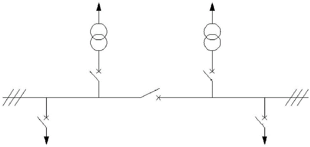
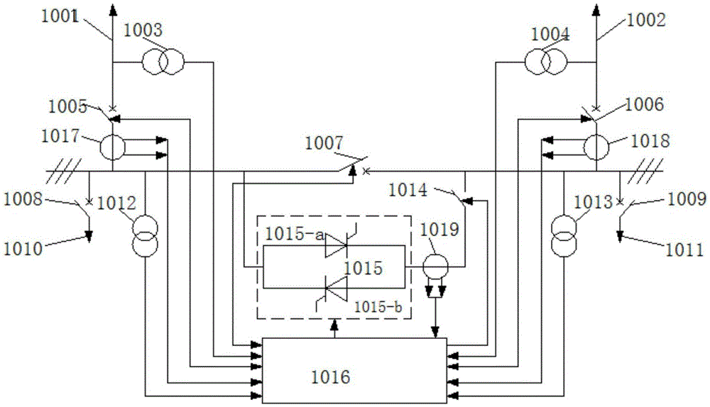
[0079] Such as figure 1 As shown, the existing fast switching device uses a high-voltage fast switch to realize power switching when a fault occurs. Due to the inherently long closing time of the vacuum circuit breaker, the rapidity of switching is greatly limited. The technical solution of the present invention proposes a thyristor The switch module 1015 is connected in parallel to the section switch 1007 to quickly turn on the thyristor switch module 1015 at the moment of power failure, and realize switching between dual power supplies. The thyristor switch module 1015 is designed to connect the switch cabinet the fastest before turning on the section switch 1007 (due to the mechanical closing of the section switch 1007, the time is much longer than that of the thyristor solid state switch in milliseconds) in the event of a fault. One or two busbars. Since the thyristor switch module 1015 is connected in parallel to the section switch 1007, the working time of the thyristor...


PUM


Abstract

The invention relates to a dual-power-supply rapid switching method and apparatus through a silicon controlled rectifier. Rapid and successful switching for the dual power supplies in a 12kV power supply system can be carried out through a silicon controlled rectifier switching module; and the switching method and apparatus is suitable for large-scale power utilization enterprises having high requirements on electric power continuity and reliability, such as petrochemical engineering, smelting, mining and the like. The dual-power-supply rapid switching method is characterized by comprising the following steps of (1) connecting two sections of buses that are used in a standby manner for each other through a section switch (1007); and (2) when one section of the bus is in fault, disconnecting an input main switch on one side of the fault bus firstly; then communicating the silicon controlled rectifier switching module (1015); and communicating the section switch (1007) after current, passing through the silicon controlled rectifier switching module (1015), is detected. According to the method and the apparatus, the silicon controlled rectifier switching module can be used to replace a vacuum circuit breaker in the 12kV high voltage dual-power-supply momentary rapid switching process so as to most quickly realize the dual-power-supply switching and to automatically recover the load input voltage.

Description

technical field [0001] The invention relates to a method and device for quick switching of dual power supplies of thyristors, which can enable a thyristor switch module to quickly and successfully switch dual power supplies in a 12kV power supply system, and is suitable for power continuity in petrochemical, smelting, mines, etc. And large-scale electricity enterprises with high reliability requirements. Background technique [0002] In the high-voltage power supply system, in order to ensure the continuity and reliability of power supply, enterprises widely use backup self-switching or microcomputer factory power fast switching devices to realize the switching between dual power supplies that are mutually backup (see attached figure 1 ). [0003] Among them, the backup self-injection device adopts a microcomputer comprehensive protection device, and the auxiliary contact of the main power supply switch starts directly (or through a low-voltage relay, a delay relay) to star...

Claims


Application Information

Patent Timeline
Patent Type & Authority Applications(China)
IPC IPC(8): H02J9/02
CPCH02J9/02Y02B70/30Y04S20/20
Inventor 杜瑞王志刚张圆鲍伟
Owner NINGXIA KAICHEN ELECTRIC GROUP
Why Eureka
Try Eureka