Rotation shaft deflection type permanent magnet power generator

A technology for permanent magnet generators and generators, applied in the direction of magnetic circuits, electric components, electrical components, etc., can solve the problems of reporting and effective application of permanent magnet generators without shaft deflection, achieve easy rectification and storage of electric energy, and improve wind energy Utilization rate, effect of improving transmission performance

Active Publication Date: 2016-05-04
HEBEI UNIVERSITY OF SCIENCE AND TECHNOLOGY
View PDF2 Cites 4 Cited by
  • Summary
  • Abstract
  • Description
  • Claims
  • Application Information

AI Technical Summary

Problems solved by technology

[0004] At present, there are no reports and effective applications of shaft deflection permanent magnet generators

Method used


Image

  • Rotation shaft deflection type permanent magnet power generator
  • Rotation shaft deflection type permanent magnet power generator
  • Rotation shaft deflection type permanent magnet power generator

Examples


Embodiment Construction

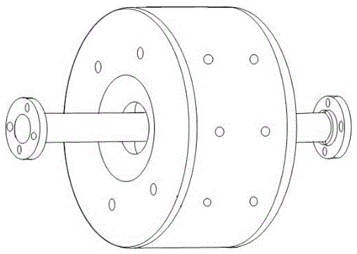
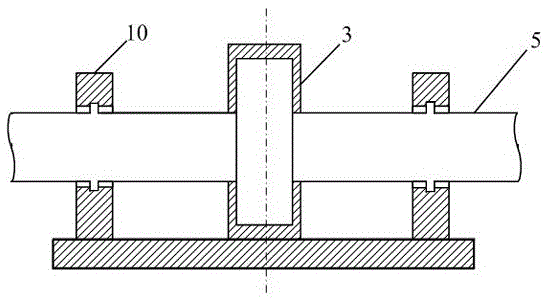
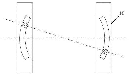
[0038] See attached Figure 1-12 ,The shaft deflection permanent magnet generator is characterized in that it mainly includes a stator, a rotor and a generator casing, the stator is fixed on the generator casing, the stator is on the periphery of the rotor, and the rotor includes an annular rotor yoke inner core made of magnetically conductive material 2. A rotating shaft 5 is fixed at the center of the rotor yoke inner core 2, a number of rotor permanent magnets 1 are distributed around the rotor yoke inner core 2, and the N pole and S pole of each rotor permanent magnet 1 in the circumferential direction Arranged in a staggered manner, a magnetic isolation piece 9 made of a non-magnetic material is provided between two adjacent rotor permanent magnets 1; a stator slot is provided on the inner surface of the stator, and a distributed winding 6 is embedded in the slot, and the generator is in power generation state; the opposite side of the stator to the rotor is in a concave...


PUM


Abstract

The invention provides a rotation shaft deflection type permanent magnet power generator, relating to the technical field of a power generator. A stator is arranged at the periphery of a rotor, the rotor comprises an annular rotor magnetic yoke inner core, the annular rotor magnetic yoke inner core is made of a magnetic conduction material, a plurality of rotor permanent magnets are arranged on the periphery of the rotor magnetic yoke inner core, N poles and S poles of all rotor permanent magnets in a circumferential direction are alternatively arranged, a magnetic isolation sheet made of a non-magnetic conduction material is arranged between each two adjacent rotor permanent magnets, a stator groove is arranged on the inner side surface of the stator, a distributed winding is embedded into the groove, a side, opposite to the rotor, of the stator is of a concave surface shape, and the rotation shaft is a dual-sided or single-sided shaft and connected with the rotor magnetic yoke inner core. The rotation shaft deflection type permanent magnet power generator still can normally generate power when the rotor deflects, namely, a certain angle is formed between the axial line of the rotor and the axial line of the stator; the rotation shaft deflection type permanent magnet power generator has the advantages of stable power generation, simplicity in structure and relatively low cost; with the additional arrangement of a concentrated winding for deflection, a power-driven state can be entered in short time when the deflection angle of the rotor is required to be actively adjusted; and the rotation shaft deflection type permanent magnet power generator can be widely applied to the fields of wind driven power generation, vehicles and the like.

Description

technical field [0001] The invention patent relates to the technical field of generators. Background technique [0002] The realization of multi-degree-of-freedom motion is currently considered more in electric motors, and motors with structures such as DC, stepping, synchronous, reluctance, induction, and ultrasonic have appeared successively. However, in the field of generators, the The innovative design and application of multi-degree-of-freedom-driven thinking is of great significance and value, and there is little special research and design. For multi-degree-of-freedom transmission, etc., the traditional method is to use multiple single-degree-of-freedom drive elements to cooperate with mechanical transmission devices, which will easily lead to a decrease in accuracy and efficiency, and often have a large volume and high cost. In traditional generators, the drive shaft is required to have a strict vertical relationship with the plane of the generator where the stator ...

Claims


Application Information

Patent Timeline
Patent Type & Authority Applications(China)
IPC IPC(8): H02K1/27H02K1/16
CPCH02K1/16H02K1/2733
Inventor 李争
Owner HEBEI UNIVERSITY OF SCIENCE AND TECHNOLOGY
Why Eureka
Try Eureka