
Continuous stepping device for screw plate of filter

A filter and screw plate technology is applied in the field of filter screw plate continuous stepping devices, which can solve the problems of wasting manpower and material resources, increasing production costs of molds and equipment, and cumbersome production processes, and achieving a solution space. Limitation, reducing equipment production costs, saving production and maintenance costs

Inactive Publication Date: 2016-05-11
BENGBU CITY MINGWEI FILTER CO LTD
View PDF11 Cites 2 Cited by
  • Summary
  • Abstract
  • Description
  • Claims
  • Application Information

AI Technical Summary

Problems solved by technology

[0002] The filter screw plate is one of the important components of the filter. The main structure of the screw plate is an extruded screw body. The screw body includes a connecting cylinder and an outer edge plate. The opening, the oil inlet and the installation hole, among which the oil inlet on the screw plate is the channel where the oil enters. The stamping die currently used uses a press to apply an external force to the material in the mold to cause it to deform or separate. The screw plate The processing process is divided into six processes: primary punching, pre-forming, secondary punching, bracting, tertiary punching and final forming, followed by material export and cutting steps. Each process requires a specific mold to be carried out separately. And its follow-up steps also need specific equipment to continue processing. Therefore, the production process of a screw plate is not only cumbersome, but also wastes manpower and material resources. More molds and equipment increase production costs and maintenance. cost, which seriously restricts its development

Method used


Image

  • Continuous stepping device for screw plate of filter
  • Continuous stepping device for screw plate of filter
  • Continuous stepping device for screw plate of filter

Examples


Embodiment Construction

[0021] The present invention will be further described below in conjunction with the accompanying drawings.

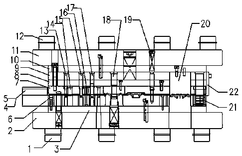
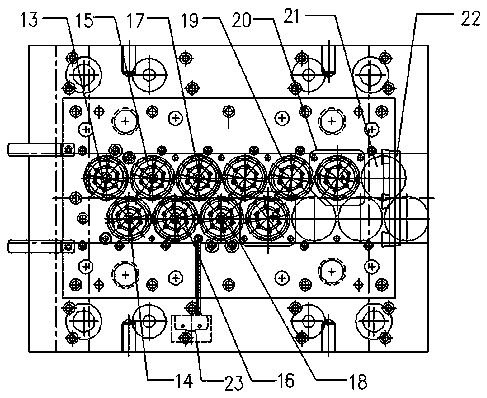
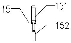
[0022] Such as Figure 1-2 As shown in , a filter screw plate continuous stepping device includes a frame, and the frame is sequentially provided with a lower pad iron 1, a lower template 2, a lower pad 3, a concave template 6, and a discharge plate from bottom to top. 7. Unloading back plate 8, fixed plate 9, upper backing plate 10, upper formwork 11, upper pad iron 12, a plate conveying device 24 is arranged between the concave formwork 6 and the unloading plate 7, and the plate conveying device 24 presses It is set to continuously convey plates between adjacent processes in a step-by-step manner. A guide block I4 and a guide block II5 are provided at the front end of the plate conveying device 24. Between the upper template 11 and the lower template 2 according to the corresponding process From left to right, there are φ6 punching assembly 13, φ13 forming die assem...


PUM


Abstract

The invention discloses a continuous stepping device for a screw plate of a filter. The continuous stepping device comprises a rack which is sequentially provided with lower pad iron, a lower die plate, a lower base plate, a concave die plate, a discharging plate, a discharging backing plate, a fixing plate, an upper base plate, an upper die plate and upper pad iron from bottom to top. A plate conveying device is arranged between the concave die plate and the discharging plate. A first material guiding block and a second material guiding block are arranged at the front end of the plate conveying device. A phi 6 punching assembly, a phi 13 forming die assembly, a phi 8.05 punching assembly, a budding die assembly, a phi 9 punching assembly, a forming die assembly, a blanking die assembly, an inner guide sleeve assembly and a cutting assembly are sequentially arranged between the upper die plate and the lower die plate from left to right according to the corresponding processes. Compared with the prior art, the continuous stepping device for the screw plate of the filter has the following advantages that relevant machining modules for manufacturing the screw plate are equipped on one device, by combining the stepping conveying device, material movement of the screw plate is achieved according to the set step pitch, and therefore automatic machining is completed, the production cost and the maintenance cost are reduced, production benefits of enterprises are increased, and popularizing is convenient.

Description

technical field [0001] The invention belongs to the technical field of automation machinery, and in particular relates to a filter screw plate continuous stepping device. Background technique [0002] The filter screw plate is one of the important components of the filter. The main structure of the screw plate is an extruded screw body. The screw body includes a connecting cylinder and an outer edge plate. The opening, the oil inlet and the installation hole, among which the oil inlet on the screw plate is the channel where the oil enters. The stamping die currently used uses a press to apply an external force to the material in the mold to cause it to deform or separate. Among them, the screw plate The processing process is divided into six processes: primary punching, pre-forming, secondary punching, bracting, tertiary punching and final forming, followed by the steps of material export and cutting. Each process requires a specific mold to be carried out separately. And i...

Claims


Application Information

Patent Timeline
Patent Type & Authority Applications(China)
IPC IPC(8): B21D35/00B21D37/10B21D28/14B21D28/34B21C51/00B21D45/08
CPCB21D35/002B21C51/00B21D28/14B21D28/34B21D35/001B21D37/10B21D45/08
Inventor 陈明志林泽强孙有为孙本胜袁同庆
Owner BENGBU CITY MINGWEI FILTER CO LTD
Learn More