Stacking manipulator for machine room floor production

A machine room floor and manipulator technology, which is applied in the field of palletizing manipulators, can solve problems such as not being suitable for the needs of industry users, and achieve the effect of simple structure, convenient use, and reliable and stable palletizing

Inactive Publication Date: 2016-05-11
JIANGSU HAOLIN AUTOMATION TECH CO LTD
View PDF7 Cites 28 Cited by
  • Summary
  • Abstract
  • Description
  • Claims
  • Application Information

AI Technical Summary

Problems solved by technology

Common palletizers on the market ...

Method used


Image

  • Stacking manipulator for machine room floor production
  • Stacking manipulator for machine room floor production
  • Stacking manipulator for machine room floor production

Examples


Embodiment

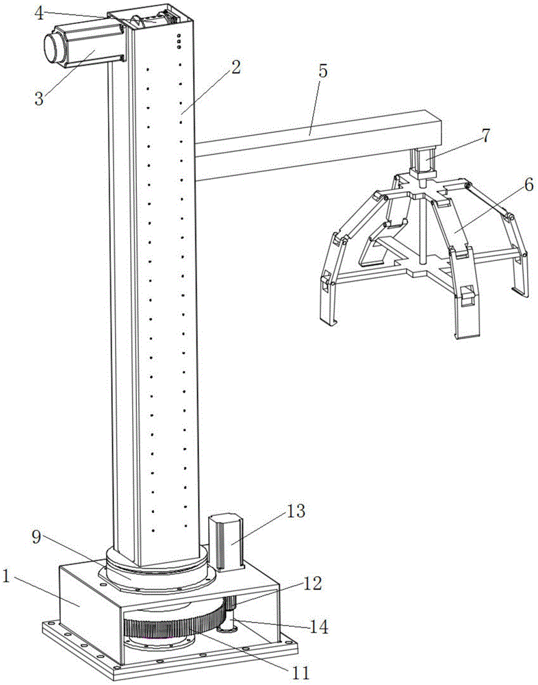
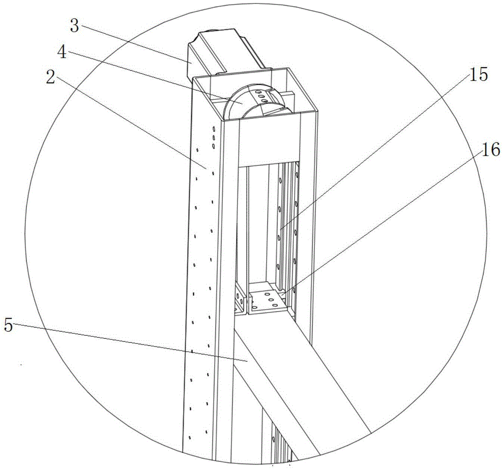
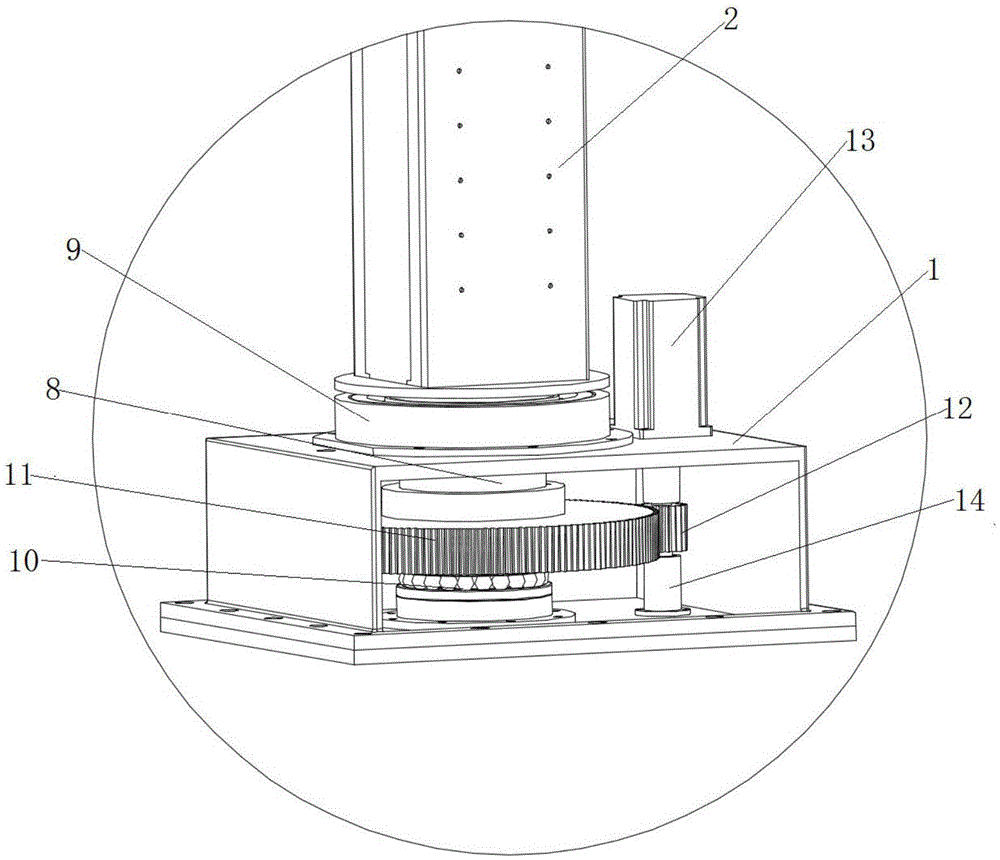
[0023] combine figure 1 , figure 2 with image 3 , a palletizing manipulator for machine room floor production in this embodiment includes a base 1, a column 2, a rotary mechanism, a lifting mechanism and a beam 5, the column 2 is vertically installed on the base 1 through the rotary mechanism, and the column 2 is controlled by the rotary mechanism In this embodiment, the rotary mechanism includes a rotary shaft 8, a thrust bearing 10, a driven gear 11, a driving gear 12, a rolling bearing installed on the top plate of the base 1 through a rolling bearing seat 9, and a rotary drive motor fixed on the top plate of the base 1 13. The upper end of the rotary shaft 8 is fixedly connected with the column 2, and the lower end of the rotary shaft 8 passes through the rolling bearing, the top plate of the base 1, the driven gear 11 and the thrust bearing 10 in sequence, and then connects with the bottom plate of the base 1 through the flange seat; the rotary drive motor 13 After pa...


PUM


Abstract

The invention discloses a stacking manipulator for machine room floor production. The stacking manipulator comprises a base, a stand column, a revolving mechanism, a lifting mechanism and a cross beam; the stand column is vertically mounted on the base through the revolving mechanism; the tail end of the cross beam is perpendicularly mounted in a chute of the stand column through the lifting mechanism; a telescopic cylinder is fixedly mounted at the bottom of the front end of the cross beam; and the tail end of an extension rod of the telescopic cylinder is connected with a four-jaw manipulator controlled to open or close by the telescopic cylinder. The stacking manipulator is simple in structure and reliable and stable in stacking, saves the labor force, has no adhesive effect destruction risk in the stacking process, and can realize double-station stacking under the condition of not increasing any hardware to supply enough time for evacuation of stacked materials.

Description

technical field [0001] The invention relates to a palletizing manipulator, more specifically, to a palletizing manipulator for machine room floor production. Background technique [0002] Machine room floor manufacturers are generally small in scale and low in automation. Due to the particularity of the machine room floor, its weight is heavy, and the palletizing work in the production process is labor-intensive. The general-purpose palletizers on the market do not meet the needs of industry users. Contents of the invention [0003] 1. The technical problem to be solved by the invention [0004] The purpose of the present invention is to overcome the above-mentioned deficiencies and provide a palletizing manipulator for machine room floor production. The technical solution of the present invention has simple structure, reliable and stable palletizing, labor saving, and no damage to the adhesive effect during the palletizing process. The risk of double-station palletizin...

Claims


Application Information

Patent Timeline
IPC IPC(8): B25J9/00B25J15/10B65G61/00
CPCB25J9/0009B25J15/10B65G61/00
Inventor 葛浩勇刘亚俊朱丰沛韩宗晨马璧
Owner JIANGSU HAOLIN AUTOMATION TECH CO LTD
Why Eureka
Try Eureka