Pipe mold cleaning mechanism and pipe mold cleaning machine

A cleaning mechanism and cleaning machine technology, applied in the field of construction, can solve the problems of time-consuming and labor-intensive, low degree of automation, quality problems of pipe piles, etc., and achieve the effects of good cleaning effect, high degree of automation and convenient cleaning.

Active Publication Date: 2016-05-11
浙江兆弟技术有限公司
View PDF6 Cites 20 Cited by
  • Summary
  • Abstract
  • Description
  • Claims
  • Application Information

AI Technical Summary

Problems solved by technology

After the whole process is completed, the pipe mold needs to be cleaned. If it is not cleaned or cleaned completely, it will have a negative impact on the next production of pipe piles, and in severe cases, it will also cause quality problems of pipe piles
[0003] The existing technology usually uses manual cleaning, that is, brushing the pipe mold with a brush. This operation method has a low degree of automation and is time-consuming and laborious.

Method used


Image

  • Pipe mold cleaning mechanism and pipe mold cleaning machine
  • Pipe mold cleaning mechanism and pipe mold cleaning machine
  • Pipe mold cleaning mechanism and pipe mold cleaning machine

Examples


Embodiment 1

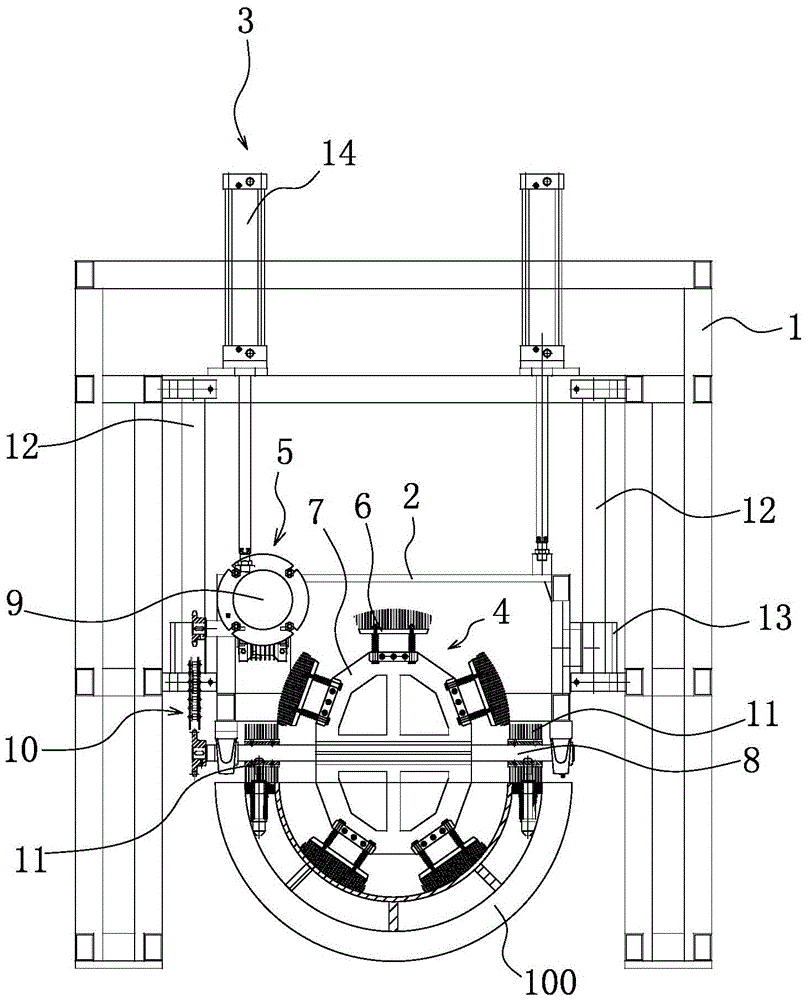
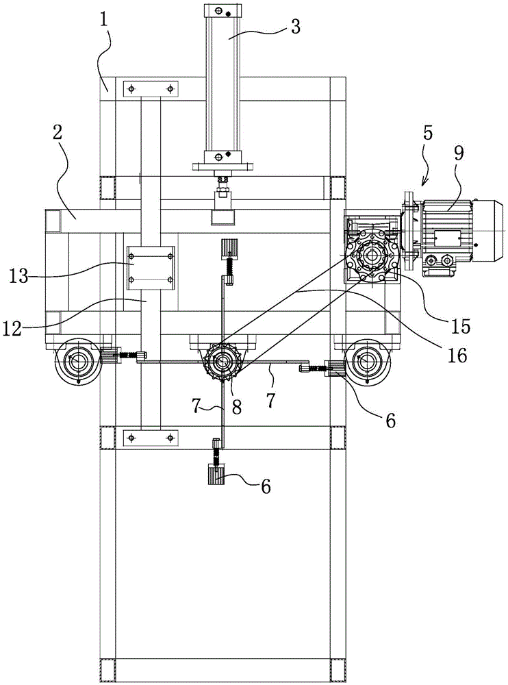
[0024] Such as Figure 1-2 As shown, a pipe mold cleaning mechanism includes a frame 1, a brush frame 2 that is movably connected with the frame 1 is provided in the frame 1, and a brush frame 2 that can drive the brush frame 2 along the vertical direction is fixed on the frame 1. The reciprocating brush frame drive mechanism 3, the brush frame 2 is rotatably connected with a brush plate assembly 4 with a number of brushes 6 fixed on the edge, when the brush frame 2 moves down, the brushes 6 can contact the inner wall of the pipe mold 100, so The above brush holder 2 is also fixed with a brush drive mechanism 5 capable of driving the brush assembly 4 to rotate. Those skilled in the art should understand that the brush 6 can be a hair brush or a metal brush, but the hardness of the bristles should be less than that of the pipe mold 100, so as to prevent the pipe mold 100 from being scratched. Preferably, the brush 6 is a copper brush. Those skilled in the art should also under...

Embodiment 2

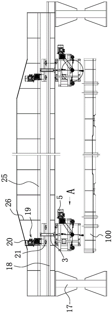
[0032] This embodiment provides a pipe mold cleaning machine, the structure and working principle are basically the same as in Embodiment 1, the difference is that, as Figure 3-4 As shown, the pipe mold cleaning machine includes a beam frame 17, a guide rail 18 is fixed on the beam frame 17, the frame 1 is slidably connected with the guide rail 18, and the frame 1 is fixed with a drive frame 1 along the The frame drive mechanism 19 for axially reciprocating movement of the guide rail 18 . That is to say, when the pipe mold 100 is fixedly placed on the ground, the pipe mold 100 can be completely cleaned by driving the frame 1 to reciprocate through the frame driving mechanism 19 .

[0033] Frame driving mechanism 19 comprises the frame driver 20 that is fixed on the frame 1 and some frame rotating shafts 21 that are rotationally connected with frame 1, and frame driver 20 can be motor, also can be hydraulic motor, wherein a frame rotating shaft 21 and the frame driver 20 are ...


PUM


Abstract

The invention belongs to the technical field of buildings, and relates to a pipe mold cleaning mechanism and a pipe mold cleaning machine. The pipe mold cleaning mechanism comprises a frame; a brush rack movably connected with the frame is arranged in the frame; the frame is fixed with a brush rack driving mechanism capable of driving the brush rack to perform a reciprocating motion in the vertical direction; the brush rack is rotationally connected with a brush disc component fixed with multiple brushes on the edge; the brush frame is additionally fixed with a brush disc driving mechanism capable of driving the brush disc component to rotate; a guide rail is fixed on a cross beam frame; the frame is slidingly connected with the guide rail; and the frame is additionally fixed with a frame driving mechanism capable of driving the frame to perform a reciprocating motion in the axial direction of the guide rail. The pipe mold cleaning mechanism is high in automation degree, convenient and fast in pipe mold cleaning, excellent in cleaning effect and suitable for an automatic production line.

Description

technical field [0001] The invention belongs to the technical field of construction and relates to a pipe mold cleaning mechanism and a pipe mold cleaning machine. Background technique [0002] In the pipe pile production industry, pipe molds are needed. The existing pipe molds are usually composed of two half molds, which are called upper mold and lower mold in the industry. The slurry is put into the lower mold, and the upper mold is closed. It is fixed with the lower mold, and the pipe pile is obtained after the steps of stretching, centrifugation, steam curing, and demoulding. The mold can separate the pipe pile from the lower mold. After the whole process is completed, the pipe mold needs to be cleaned. If it is not cleaned or the cleaning is incomplete, it will have a negative impact on the next production of pipe piles, and in severe cases, it will also lead to quality problems of pipe piles. [0003] In the prior art, manual cleaning is usually used, that is, brush...

Claims


Application Information

Patent Timeline
Patent Type & Authority Applications(China)
IPC IPC(8): B28B7/38B08B1/04B08B1/00B08B13/00
CPCB08B1/002B08B1/04B08B13/00B28B7/386
Inventor 周兆弟
Owner 浙江兆弟技术有限公司
Why Eureka
Try Eureka