Pneumatic tire

A technology of pneumatic tires and tires, applied in tire parts, tire tread/tread pattern, transportation and packaging, etc., can solve problems such as water drift

Active Publication Date: 2016-05-11
SUMITOMO RUBBER IND LTD
View PDF6 Cites 24 Cited by
  • Summary
  • Abstract
  • Description
  • Claims
  • Application Information

AI Technical Summary

Problems solved by technology

Therefore, the pneumatic tire of Patent Document 1 has a problem that water drifting tends to occur near the inner shoulder main groove of the ground contact surface.

Method used


Image

  • Pneumatic tire
  • Pneumatic tire
  • Pneumatic tire

Examples


Embodiment

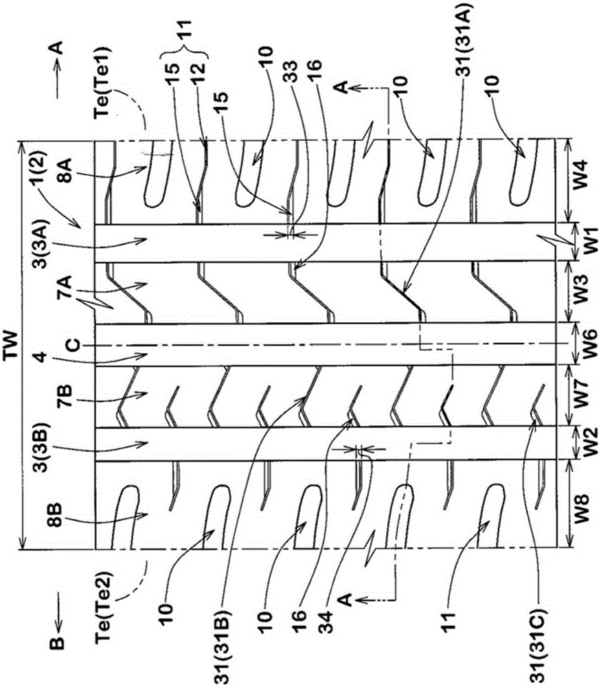
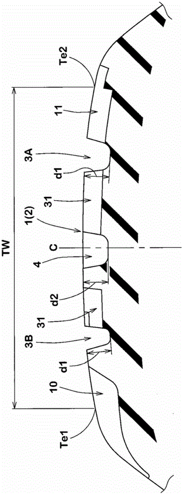
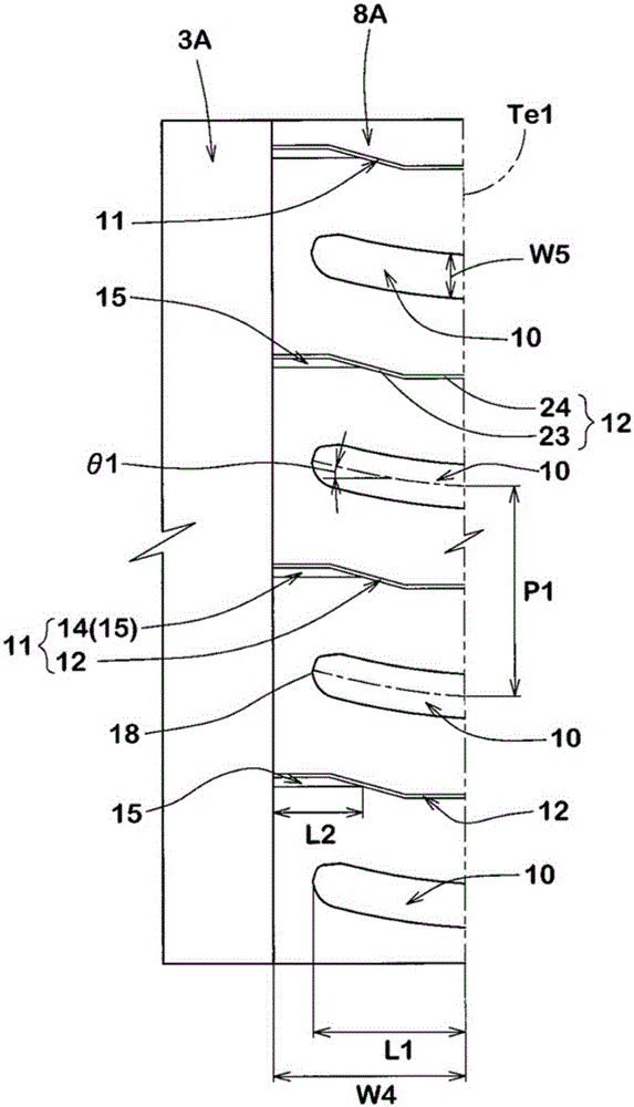
[0097] Prototyped according to the specifications in Table 1 with figure 1 Pneumatic tires of size 165 / 70R14 with the basic tread pattern in As Comparative Example 1, such as Figure 8 As shown, a pneumatic tire in which the groove width W1 of the inner shoulder main groove 3A is smaller than the groove width W2 of the outer shoulder main groove 3B and in which the shoulder lateral groove 10 communicates with each shoulder main groove was trial-produced. The handling stability and wet road performance of each test tire were tested on a dry road surface. The general specifications and test methods of each test tire are as follows.

[0098] Mounting rim: 14×5J

[0099] Tire internal pressure: 230kPa

[0100]

[0101] The steering stability when the following test vehicles were driven on an asphalt circuit course was evaluated based on the driver's sensory experience. The results are expressed by taking the result of Comparative Example 1 as 100. As a result, the larger th...


PUM


Abstract

A pneumatic tire (1) comprises a tread portion (2) having an inboard tread edge (Tel) to be positioned towards the center of a vehicle body, and an outboard tread edge (Te2) to be positioned away from the center of the vehicle body. The tread portion (2) is provided with an inboard shoulder main groove (3A), an outboard shoulder main groove (3B) and a center main groove (4) to define an inboard shoulder land region (8A) and an inboard middle land region (7A). The width W1 of the inboard shoulder main groove (3A) is more than the width W2 of the outboard shoulder main groove (3B) and in a range of from 9.0 % to 10.0 % of the tread width (TW). The ratio W4/W3 of the width W4 of the inboard shoulder land region (8A) to the width W3 of the inboard middle land region (7A) is in a range of from 1.3 to 1.4. The inboard shoulder land region (8A) is provided with shoulder lateral grooves (10) extending axially inwardly from the inboard tread edge (Tel) to terminate within the inboard shoulder land region (8A). The ratio W5/P1 of the width w5 of the shoulder lateral grooves (10) to an arrangement pitch P1 of the shoulder lateral grooves (10) is in a range of from 0.18 to 0.25.

Description

technical field [0001] The present invention relates to a pneumatic tire which improves handling stability on a dry road surface and wet road performance in a balanced manner. Background technique [0002] For example, Patent Document 1 below proposes a pneumatic tire in which the direction of installation to a vehicle is specified. In the pneumatic tire of Patent Document 1, the outer shoulder main groove positioned outside the vehicle when mounted on the vehicle has a groove width larger than the inner shoulder main groove positioned inside the vehicle when mounted on the vehicle. [0003] In such a pneumatic tire, high drainage performance can be expected in the outer shoulder main groove, but the drainage performance of the inner shoulder main groove is low. On the other hand, a pneumatic tire is usually attached to a vehicle so as to form a negative camber angle. Therefore, there occurs a tendency that the tire circumferential length of the contact patch is larger on ...

Claims


Application Information

Patent Timeline
Patent Type & Authority Applications(China)
IPC IPC(8): B60C11/03
CPCB60C11/0304B60C11/0306B60C11/1236B60C2011/0344B60C2011/0353B60C2011/036B60C2011/0365B60C2011/0386
Inventor 永濑将弘
Owner SUMITOMO RUBBER IND LTD
Why Eureka
Try Eureka