

Heat treatment method for Al-Si-Cu-Mg casting alloy
A technology of al-si-cu-mg, heat treatment method, applied in the field of metallurgy, can solve the problems of the decline of the mechanical properties of the alloy, the over-burning of the alloy, etc.
Active Publication Date: 2016-05-11
BEIHANG UNIV +1
View PDF9 Cites 12 Cited by
- Summary
- Abstract
- Description
- Claims
- Application Information
AI Technical Summary
Problems solved by technology
However, if the solid solution temperature is too high, it will lead to local over-burning of the alloy, and the mechanical properties of the alloy will drop sharply. Gradually, this contradiction has escalated into a barrier in the industry, so for Al-Si-Cu-Mg The ratio of element selection and the temperature and time parameters used for the corresponding two-stage solid solution and two-stage aging have become the main focus of alloy producers to improve product quality and save production costs.
Method used
View moreImage
Smart ImageViewing Examples

Examples
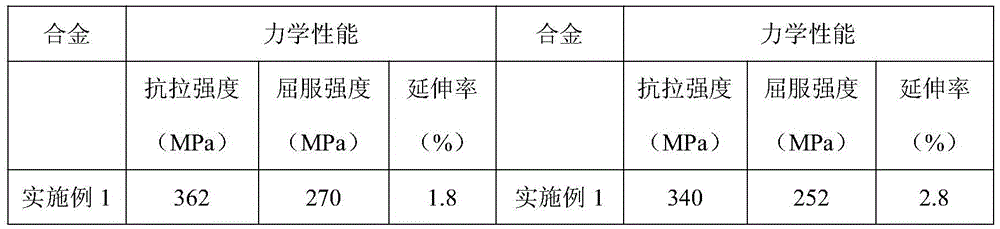
Embodiment 1
[0034] The temperature of the secondary aging treatment is 200°C, and the treatment time is 1h.
Embodiment 2
[0036] The temperature of the secondary aging treatment is 200°C, and the treatment time is 2h.
Embodiment 3
[0038] The temperature of the secondary aging treatment is 200°C, and the treatment time is 5h.
Login to View More PUM
 Abstract
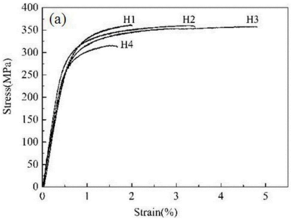
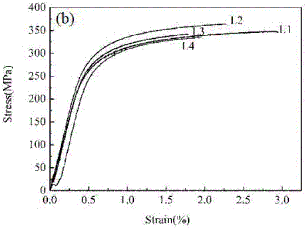
The invention relates to Al-Si-Cu-Mg casting alloy. The Al-Si-Cu-Mg casting alloy is formed by smelting electrolytic aluminum, silicon metal, pure magnesium and Al-Cu intermediate alloy and comprises, by weight, 5.5%-6.5% of Si, 1.8%-2.2% of Cu, 0.45%-0.55% of Mg and the balance Al, and the ratio of the Cu to the Mg is 4:1. The Al-Si-Cu-Mg casting alloy is subjected to two-stage solid solution treatment and two-stage aging treatment, it can be ensured that precipitated phases of the Al-Si-Cu-Mg casting alloy are all dissolved in a matrix through suitable solid solution temperature and time, and overburning of crystal boundaries cannot be caused; and then the characteristics and mechanical properties precipitated by the alloy phases are controlled through two-stage aging treatment, so that the tensile property of the Al-Si-Cu-Mg casting alloy obtained through the method is obviously improved in index compared with the tensile property of Al-Si-Cu-Mg casting alloy subjected to T6 treatment.
Description
technical field [0001] The invention relates to the technical field of metallurgy, in particular to a heat treatment method for an Al-Si-Cu-Mg casting alloy. Background technique [0002] The typical heat treatment method for Al-Si alloy used in sand mold and gravity casting is T6 heat treatment, which mainly includes: [0003] 1. Solid solution treatment is carried out at a higher temperature to dissolve the formed Cu-rich and Mg-rich phase particles to obtain a highly uniform alloy composition. [0004] 2. Quenching treatment. Generally, quenching at room temperature is used to obtain a supersaturated solid solution of solid solution atoms and vacancies. [0005] 3. Age hardening treatment, at room temperature (natural aging) or elevated temperature (artificial aging), the strengthening phase is precipitated from the supersaturated solid solution. [0006] The temperature of solution treatment is generally selected close to the eutectic point temperature of the alloy, wh...
Claims
Login to View More Application Information
Patent Timeline
 IPC IPC(8): C22C21/02C22F1/043
CPCC22C21/02C22F1/043
Inventor马朝利徐聪肖文龙郑岩王成远张建斌蔡振斌胡晓亮杨明娟杨海军刘志国
OwnerBEIHANG UNIV