Temporary pier construction method adopting assembled heavy steel pipe supporting device

A steel pipe support and construction method technology, which is applied in the erection/assembly of bridges, bridges, buildings, etc., can solve the problems of weak structural strength support capacity, increased construction cost, and increased construction cost, so as to reduce installation difficulty and construction cost , Reduce construction cost, reduce the effect of assembly difficulty

Active Publication Date: 2016-05-11
GUANGXI ROAD & BRIDGE ENG GRP CO LTD
View PDF8 Cites 4 Cited by
  • Summary
  • Abstract
  • Description
  • Claims
  • Application Information

AI Technical Summary

Problems solved by technology

For the temporary pier of concrete structure, it has good structural strength, but its construction process is similar to that of the permanent pier. The whole construction process has many procedures, which not only requires a lot of man-hours, but also greatly increases the construction cost. Finally, in the process of dismantling the temporary pier, a large amount of manpower and material resources are also required, which greatly increases the construction cost; for the truss type temporary pier, its structure is simple, easy to install and easy to dismantle, which not only saves the cost, but also shortens the construction time. The construction period is shortened, and the labor cost is reduced. However, the structural strength of this truss-type temporary pier is relatively weak in terms of its vertical support capacity and horizontal support capacity, so now this truss-type temporary pier is used; and , this kind of truss-type temporary piers, because some components are fixedly connected by welding or other forms, so when they are removed, they need to be removed in a destructive way. After the removal, these Components can no longer be reused, so there is also a certain waste, resulting in an increase in construction costs

Method used


Image

  • Temporary pier construction method adopting assembled heavy steel pipe supporting device
  • Temporary pier construction method adopting assembled heavy steel pipe supporting device
  • Temporary pier construction method adopting assembled heavy steel pipe supporting device

Examples


Embodiment 1

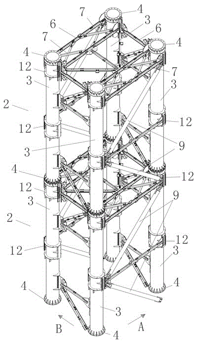
[0126] Embodiment 1: as Figure 1-8 as shown,

[0127] An assembled heavy-duty steel pipe support device, including several support segments 2 spliced ​​in sequence in the vertical direction, the support segments 2 include several vertically arranged heavy-duty steel pipes 3, the number of the heavy-duty steel pipes 3 ensures that the support device 1 has sufficient support strength in the vertical direction, and the heavy-duty steel pipes 3 are separated by a suitable distance so that the support device 1 has sufficient stability in the horizontal direction, and connecting rods are connected between the heavy-duty steel pipes 3, so There are detachable connections between the support segments 2, between the connecting rods and the heavy steel pipe 3, and between the connecting rods and the connecting rods, and the two ends of the heavy steel pipe 3 are respectively provided with Connecting end plate 4, the connecting end plate 4 is ring-shaped, surrounding the outside of the...

Embodiment 2

[0130] Embodiment 2: as Figure 1-8 as shown,

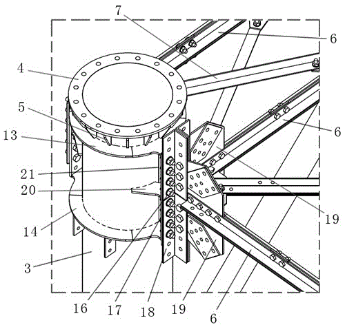
[0131] As for the assembled heavy-duty steel pipe support device described in Example 1, each support section 2 includes four heavy-duty steel pipes 3 of the same height, and the four heavy-duty steel pipes 3 cooperate with each connecting rod to form a square frame, and the support sections 2 is a rectangular parallelepiped frame structure, the connecting rod includes a cross bar 6, the cross bar 6 is perpendicular to the central axis of the heavy-duty steel pipe 3, and the two heavy-duty steel pipes 3 in the same length plane of the support segment 2, A cross bar 6 is connected between the inner side and the inner side of the upper end, and a cross bar 6 is also connected between the outer side and the outer side. The two heavy-duty steel pipes 3 in the same length plane of the support segment 2 are connected between the inner side and the inner side of the upper end. The cross bar 6 is the first cross bar 6, the cross bar 6 c...

Embodiment 3

[0133] Embodiment 3: as Figure 1-8 as shown,

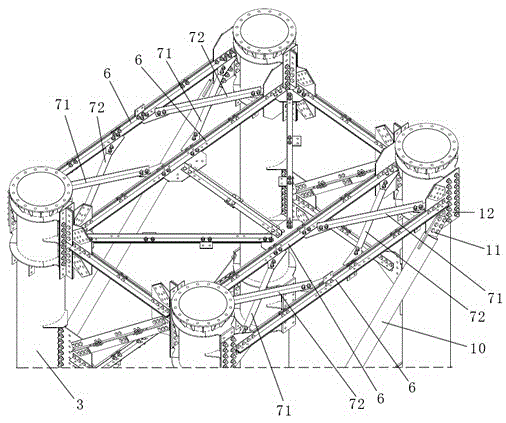
[0134] As for the assembled heavy-duty steel pipe support device described in Embodiment 2, the cross support 7 is a split structure, including a first support rod 71 and a second support rod 72 arranged crosswise, the first support rod 71 and the second support rod 72 The second support bar 72 crosses in an X shape, the first support bar 71 and the second support bar 72 are angle steel, the outer side wall of the first support bar 71 is in contact with the outer side wall of the second support bar 72, a cross bar There are two cross supports 7 in the group, each cross support 7 corresponds to a heavy steel pipe 3, two cross supports 7 in the same cross bar assembly, the first cross bar of one cross support 7 6 is parallel to the second cross bar 6 of another cross support 7. The first support bar 71 and the second support bar 72 are non-universal components, which are produced according to the size requirements of on-site assem...


PUM


Abstract

The invention relates to the technical field of bridge building construction, in particular to a temporary pier construction method. The method sequentially comprises the following steps: A: pouring a base used for supporting an assembled heavy steel pipe supporting device in a design position; B: according to a design requirement, making members of the assembled heavy steel pipe supporting device; and C: assembling the assembled heavy steel pipe supporting device on the base, wherein the height of the base ensures the assembled heavy steel pipe supporting device to have sufficient supporting strength, rigidity and stability vertically and horizontally. According to the scheme provided by the invention, the height of the base and the height of the assembled heavy steel pipe supporting device are coordinated, so that on the premise of ensuring the temporary pier to have reliable supporting strength, the construction difficulty of the temporary pier is lowered, the project time is shortened, and the construction cost and time are saved.

Description

technical field [0001] The invention relates to the technical field of bridge building construction, in particular to a temporary pier construction method using an assembled heavy-duty steel pipe support device. Background technique [0002] In the field of bridge construction technology, the jacking construction method is mostly used in the construction of continuous girder bridges and cable-stayed bridges. Specifically, the beam body is poured or assembled segment by segment on the assembly platform, and then vertically pushed with a jack to make the beam body pass through. The temporary sliding bearing surface of each pier top is adjusted and placed in place. The jacking construction is to set up the construction site on the ground behind the abutment, pour or assemble the beam body in sections, install a steel guide beam whose length is the specified ratio of the jacking span in front of the beam body, and then apply force through a horizontal jack. Push the beam forwar...

Claims


Application Information

Patent Timeline
Patent Type & Authority Applications(China)
IPC IPC(8): E01D21/00
CPCE01D21/00
Inventor 秦大燕冯智韩玉黄绍结林峰蒋玮陈林李莘哲韦强苏强玉达变
Owner GUANGXI ROAD & BRIDGE ENG GRP CO LTD
Why Eureka
Try Eureka