

Steel-encased concrete composite beam-steel pipe column connection joint
A steel pipe column and composite beam technology, applied in the direction of construction and building structure, can solve the problems of easy weakening of the steel pipe column section, large on-site welding workload, unsuitable quality assurance, etc., reducing welding workload, convenient concrete pouring, Ease of construction
- Summary
- Abstract
- Description
- Claims
- Application Information
AI Technical Summary
Problems solved by technology
Method used
Image

Examples
Embodiment 1
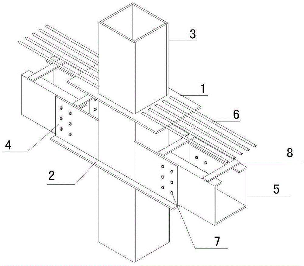
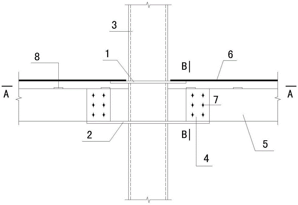
[0027] Please refer to Figure 1-9 , the present invention provides an outsourcing steel concrete composite beam-steel pipe column joint, including upper and lower through-type partitions 1, 2, steel pipe columns 3 and lateral connecting plates 4, upper and lower through-type partitions 1, 2 The horizontal penetration is set on the steel pipe column 3, the upper through-type partition 1 is used to connect the negative moment steel bar 6, the lower through-type partition 2 and the lateral connection plate 4 form a U-shaped device on the side of the column, and the outsourcing steel beam 5 is placed directly In the U-shaped device, pouring holes 10 and ventilation holes 11 are provided on the upper and lower through-type partitions 1 and 2 .
[0028] The upper and lower through-type partitions 1 and 2 are connected to the column wall of the steel pipe column 3 by welding; the upper partition 1 is located at the negative moment steel bar 6 on the top of the plate to support and w...
Embodiment 2
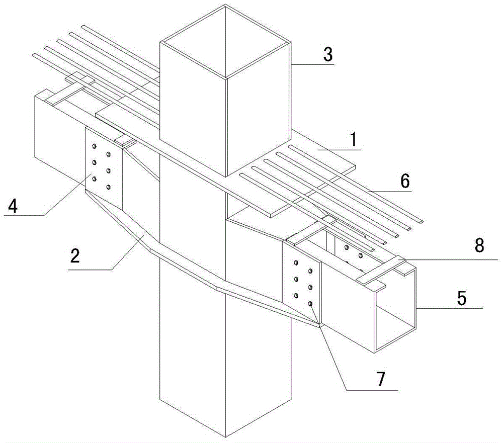
[0034] Or when the cross-sectional width of the steel pipe column 3 is greater than 50 mm or more than the cross-sectional width of the outer steel beam 5 of the composite beam, the lower through-type partition plate 2 and the lateral connecting plate 4 form a variable-section U-shaped integral device on the column side, and the rest of the structure With embodiment 1.
PUM
 Abstract
Description
Claims
Application Information