An LNG air-temperature gasification device and method for generating electricity using solar walls and temperature differences

An air-temperature gasifier and thermoelectric power generation technology, which is applied in the field of solar energy gasification of LNG, can solve the problem of low gasification capacity of the LNG air-temperature gasifier, frost and icing on the outer surface of the gasifier, and a gasification amount of up to 100%. Less than the rated value and other problems, to achieve the effect of promoting heat exchange, eliminating frost and freezing, and reducing energy consumption for gasification

Active Publication Date: 2017-08-04
NORTH CHINA ELECTRIC POWER UNIV (BAODING)
View PDF9 Cites 0 Cited by
  • Summary
  • Abstract
  • Description
  • Claims
  • Application Information

AI Technical Summary

Problems solved by technology

The advantage of the LNG air-temperature gasifier is that it directly absorbs the heat of the air in the atmosphere to gasify LNG, does not consume water and electricity, and has low operating costs, but its gasification capacity (that is, gasification capacity) is greatly affected by the ambient temperature. When the temperature is low, especially in severe cold areas, the gasification capacity may not reach the rated value, and the outer surface of the gasifier is prone to frost and ice
For this reason, the existing technologies mostly use water bath heating, electric heating, or dual-use and one-standby methods to solve the problems of low gasification capacity and easy frosting and freezing of LNG air-temperature vaporizers, but these methods not only consume energy many, and high investment
At the same time, during the gasification process of LNG, a large amount of cold energy stored in itself is not utilized, and is directly wasted to the environment

Method used


Image

  • An LNG air-temperature gasification device and method for generating electricity using solar walls and temperature differences
  • An LNG air-temperature gasification device and method for generating electricity using solar walls and temperature differences

Examples


Embodiment Construction

[0029] The present invention will be further described below in conjunction with the accompanying drawings and specific embodiments. It should be emphasized that the following description is only exemplary and not intended to limit the scope of the invention and its application.

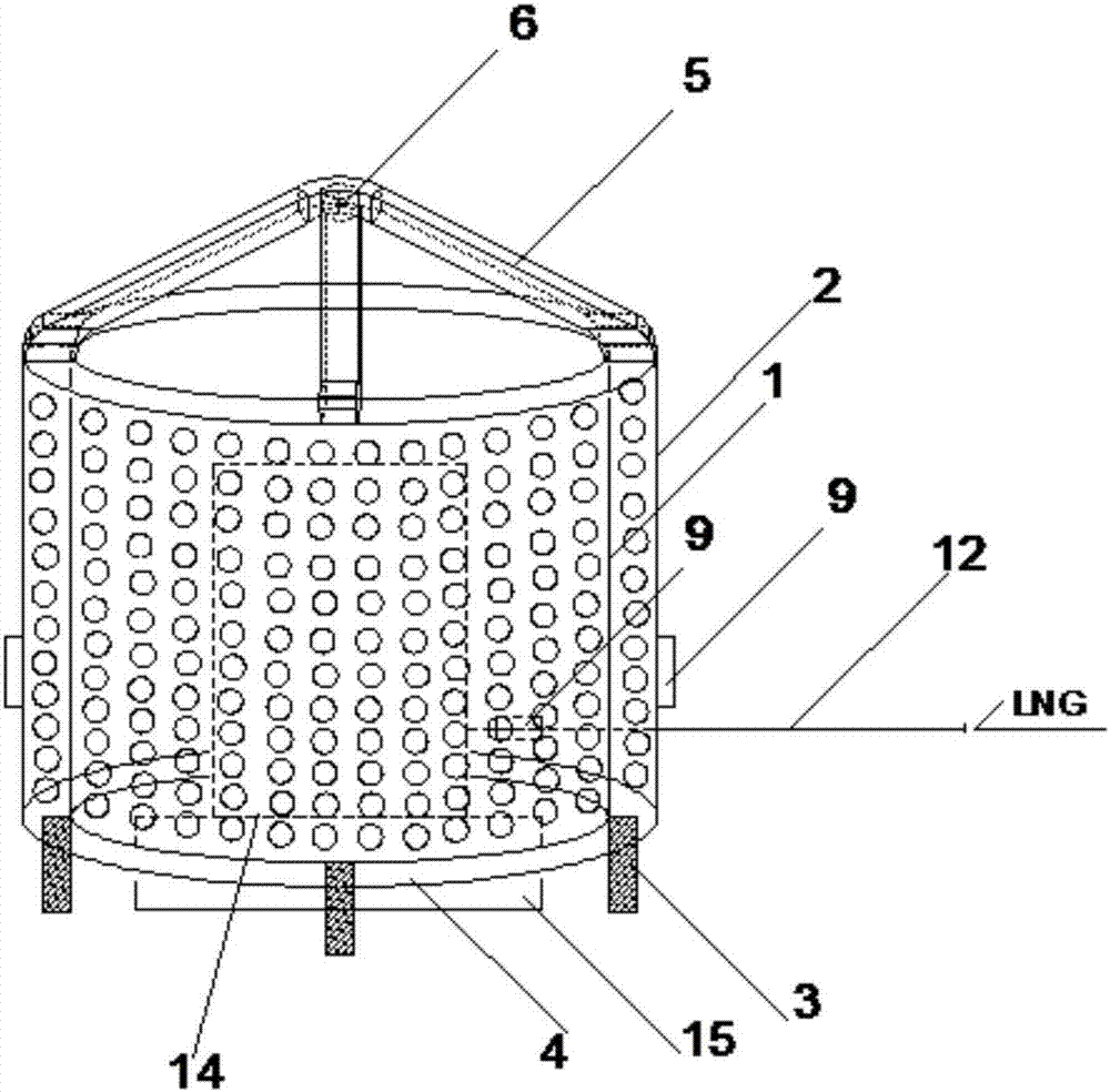
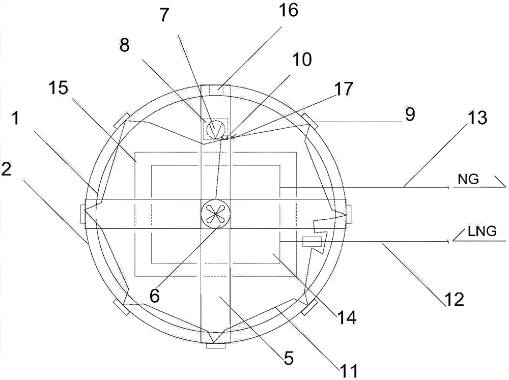
[0030] Such as Figure 1-Figure 2 Shown is an LNG air-temperature gasification device that utilizes a solar wall and a temperature difference to generate electricity. The device includes a solar wall, a thermoelectric power generation sheet 9, a fan 6, an air pipe 5, a motor 7, and an LNG air-temperature gasifier 14;

[0031] The solar wall is a cylindrical structure, including a solar wall inner panel 1 and a solar wall heat collecting plate 2 from the inside to the outside, and the solar wall inner plate 1 and the solar wall heat collecting plate 2 are made of galvanized steel, both The bottom of the solar wall is flush with the tops of the two, and the two are separated to form a solar wall cavit...


PUM


Abstract

The invention relates to an LNG air-temperature gasification device and method for generating electricity by utilizing solar walls and temperature differences. The LNG air-heated vaporizer is located inside the solar wall, and the air in the environment enters the solar wall cavity composed of the solar wall inner plate and the solar wall heat collector through the small holes on the solar wall collector plate and the bottom air inlet. The wall heat collector absorbs solar radiation to heat the air, and the air flows upward after being heated, and is collected to the inlet of the fan through the air duct, and is sent to the LNG air-temperature vaporizer to vaporize LNG after being pressurized by the fan; when there is no solar radiation at night, The heat storage function of the solar wall itself is used to heat the air for gasification of LNG; the power required by the fan is provided by the power supply formed by the thermoelectric generation sheet. The device of the invention has a simple structure, uses solar radiation combined with temperature difference power generation technology, fully utilizes solar energy, air energy and LNG cold energy, does not consume additional primary energy, is environmentally friendly and energy-saving, and is convenient for componentization and commercialization.

Description

technical field [0001] The invention belongs to the technical field of solar energy gasification of LNG, in particular to an LNG air-temperature gasification device and method for generating electricity by utilizing solar walls and temperature differences. Background technique [0002] Liquefied natural gas (LNG) is an important source of city gas in my country, which needs to be gasified from a liquid state to a gaseous state before being supplied to users. Since the temperature of LNG is -162°C, an air-temperature gasifier is often used to gasify LNG. The advantage of the LNG air-temperature gasifier is that it directly absorbs the heat of the air in the atmosphere to gasify LNG, does not consume water and electricity, and has low operating costs, but its gasification capacity (that is, gasification capacity) is greatly affected by the ambient temperature. When the temperature is low, especially in severe cold regions, the gasification capacity may not reach the rated val...

Claims


Application Information

Patent Timeline
Patent Type & Authority Patents(China)
IPC IPC(8): F17C7/04F24J2/34F24J2/04H02N11/00
CPCY02E10/44
Inventor 时国华李丹田胜楠
Owner NORTH CHINA ELECTRIC POWER UNIV (BAODING)
Why Eureka
Try Eureka