Cryogenic liquid gasification cold energy recycling device

A cryogenic liquid and cold energy recovery technology, applied in the field of heat exchange, can solve the problems of low recycling of high-quality cold energy, utilization rate not higher than 30%, and high cost of liquid refrigerant, so as to avoid waste, ensure safe production, The effect of saving cooling power

Pending Publication Date: 2018-11-06
丁斌
View PDF0 Cites 4 Cited by
  • Summary
  • Abstract
  • Description
  • Claims
  • Application Information

AI Technical Summary

Problems solved by technology

[0002] Cryogenic liquids such as LNG, liquefied natural gas, liquid oxygen, and liquid nitrogen will release a large amount of cold energy during the gasification process. At present, these cold energy are basically emptied, causing huge waste. Taking liquefied natural gas LNG as an example, one ton of -162°C LNG The value of cold energy is about 240kWh, which can maintain the cooling capacity required by 800 tons of cold storage at -20°C for one day. Therefore, if the cold energy can be recycled, its economic value is very considerable
[0003] Most of the cold energy recovery technologies in the prior art use liquid refrigerants to realize cold energy recovery. For example, some places try to use liquid refrigerants to recover cold energy through heat exchangers, that is, use liquid refrigerants to absorb vaporized cold energy through coils. Utilization, the cost of liquid refrigerants is high, and some liquid refrigerants are poisonous. The main reason is that due to the limitation of the freezing temperature of liquid refrigerants, it is powerless to recover the part of high-quality cold energy lower than -50°C, so that this part of high-quality cold energy is rarely recovered. Utilization, the overall recovery and utilization rate of gasification cold energy by using liquid refrigerant is low, generally the utilization rate is not higher than 30%, and this kind of cold energy recovery device usually needs a large amount of gasification as a support
In addition, in some special cold energy utilization occasions, such as controlled atmosphere fresh storage, the use of cold energy is to transfer and release cold energy through coils, and cool the fresh storage through circulating fans. Since this kind of device belongs to indirect refrigeration, it is bound to be subject to various Restricted by these factors, the heat transfer efficiency will be greatly reduced, and the controlled atmosphere fresh-keeping store needs to be filled with a large amount of nitrogen, which will also consume a large amount of cold energy.
At present, there is no effective cold energy recovery technology that can take into account the recovery efficiency of cold energy, the recovery cost and the adaptability to harsh cold energy utilization conditions.

Method used


Image

  • Cryogenic liquid gasification cold energy recycling device

Examples


Embodiment 1

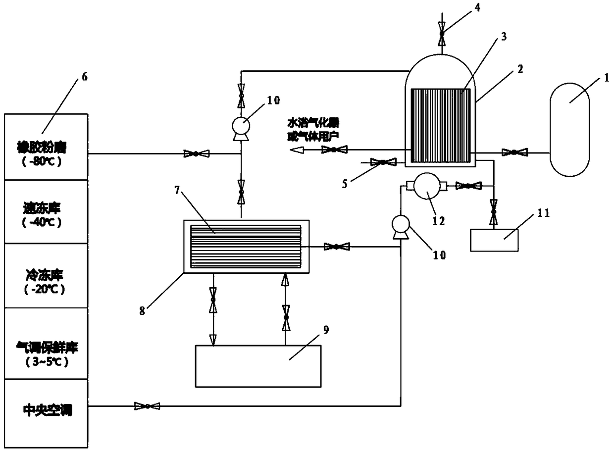
[0026] see figure 1 , figure 1 It is a cryogenic liquid gasification cold energy recovery and utilization device according to Embodiment 1 of the present invention. The device consists of a cryogenic liquid gasification system, a nitrogen circulation system and an end user to form a circulation loop. see figure 1 , the device specifically includes a cryogenic liquid storage tank 1, a nitrogen generator or a nitrogen storage container 11 and a closed nitrogen refrigerant vaporizer, the closed nitrogen refrigerant vaporizer includes a thermal insulation shell 2 and is arranged inside the thermal insulation shell 2 The heat exchanger 3 (specifically, it can be a heat exchange tube bundle group), the thermal insulation shell 2 is connected to the nitrogen generator or the nitrogen storage container 11 (specifically, it can be a nitrogen cylinder group), and the nitrogen generator or the nitrogen storage container 11 Provide circulating nitrogen gas into the heat preservation she...

Embodiment 2

[0038] According to an object of the present invention, the device should be able to adapt to small and medium-sized gasification devices as much as possible, and should also be able to adapt to multi-functional needs as much as possible. For this reason, different from the closed nitrogen refrigerant gasifier in Embodiment 1, the closed The nitrogen refrigerant vaporizer is a combination of multiple sets (not shown), which can be combined in series or in parallel. In this way, it can be flexibly designed according to the amount of gasification, which is more conducive to the cascade utilization of cold energy , the gasification effect is also better, and, under the premise of ensuring the cold energy recovery effect, the insulation shell 2 and the heat exchange tube bundle heat exchanger 3 of each set of the closed nitrogen refrigerant vaporizer can be designed to be better than The existing small size makes the overall structure of the device more compact.


PUM


Abstract

A cryogenic liquid gasification cold energy recycling device comprises a cryogenic liquid storage tank (1), a nitrogen generator or a nitrogen storage container (11) and a closed nitrogen refrigerantgasifier; the closed nitrogen refrigerant gasifier comprises an insulation shell (2) and a heat exchanger (3) arranged in the insulation shell (2), and cryogenic liquid is conveyed to a downstream secondary gasification system or directly conveyed to gas users through the heat exchanger (3) after being gasified; in this process, the heat exchanger (3) releases cold energy to nitrogen in the insulation shell (2) through heat exchange with the cryogenic liquid, and the closed nitrogen refrigerant gasifier is an assembly composed of one or more sets; the insulation shell (2) can be provided witha safety release valve (4) and a blow-down valve (5), and the output end of the insulation shell (2) is connected to a cascade cold energy user (6) and/or a liquid refrigerant system; and a nitrogen loop is used for providing circulating pressure under the control of a control system through a circulating pump (10) automatically.

Description

technical field [0001] The invention relates to the technical field of heat exchange, in particular to a cryogenic liquid gasification cold energy recovery and utilization device. Background technique [0002] Cryogenic liquids such as LNG, liquefied natural gas, liquid oxygen, and liquid nitrogen will release a large amount of cold energy during the gasification process. At present, these cold energy are basically emptied, causing huge waste. Taking liquefied natural gas LNG as an example, one ton of -162°C LNG The value of cold energy is about 240kWh, which can maintain the cooling capacity required by 800 tons of cold storage at -20°C for one day. Therefore, if the cold energy can be recycled, its economic value is very considerable. [0003] Most of the cold energy recovery technologies in the prior art use liquid refrigerants to realize cold energy recovery. For example, some places try to use liquid refrigerants to recover cold energy through heat exchangers, that is, ...

Claims


Application Information

Patent Timeline
Patent Type & Authority Applications(China)
IPC IPC(8): F25J1/02F25B41/00F25B41/40
CPCF25B41/00F25J1/0201
Inventor 丁斌
Owner 丁斌
Why Eureka
Try Eureka