Efficient incinerator

An incinerator, high-efficiency technology, applied in the direction of incinerators, combustion methods, combustion types, etc., can solve the problems of incinerators with insufficient combustion, heat that cannot be recycled, and containing harmful substances, so as to reduce the content of harmful substances and avoid waste , the effect of reducing pollution

Inactive Publication Date: 2016-05-11
CHANGZHOU JINTAN HANGUANG TECH CO LTD
View PDF0 Cites 7 Cited by
  • Summary
  • Abstract
  • Description
  • Claims
  • Application Information

AI Technical Summary

Problems solved by technology

[0003] The technical problem to be solved by the present invention is: in order to solve the problem of insufficient combustion of existing incinerators, the discharged gas contains harmful substances, and the heat generated by combustion cannot be recycled, and a high-efficiency incinerator is provided.

Method used


Image

  • Efficient incinerator

Examples


Embodiment Construction

[0012] The present invention is described in further detail now in conjunction with accompanying drawing. These drawings are all simplified schematic diagrams, which only illustrate the basic structure of the present invention in a schematic manner, so they only show the configurations related to the present invention.

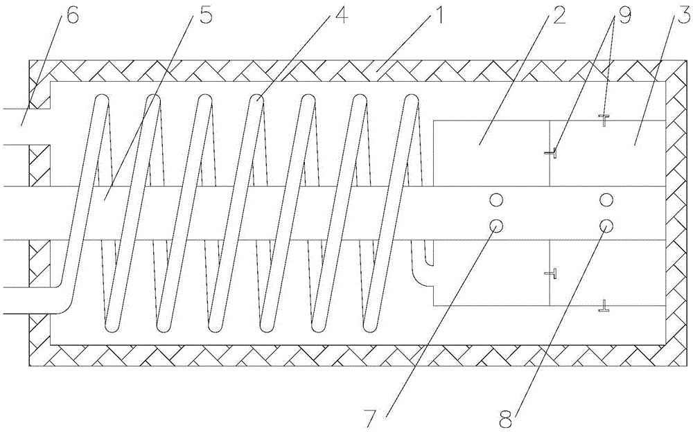
[0013] Such as figure 1 A high-efficiency incinerator shown includes a furnace shell 1, a primary combustion chamber 2, a secondary combustion chamber 3, an air pipe 5, a waste gas pipe 4 and an exhaust port 6, and the primary combustion chamber 2 and the secondary combustion chamber 3 are arranged on At the rear end of the furnace chamber, a check valve 9 is provided between the primary combustion chamber 2 and the secondary combustion chamber 3, and the air pipe 5 is arranged in the center of the inner cavity of the furnace shell 1, and the air pipe 5 enters the furnace chamber from the front end of the furnace shell 1 And run through the primary combustion...


PUM


Abstract

The invention relates to an efficient incinerator. A primary combustion chamber and a secondary combustion chamber are arranged at the back end of a furnace chamber; a check valve is arranged between the primary combustion chamber and the secondary combustion chamber; an air pipe is arranged in the center of an inner cavity of a furnace shell, enters the furnace chamber from the front end of the furnace shell and penetrates through the primary combustion chamber and the secondary combustion chamber; a first air inlet is formed in the pipe wall of the air pipe in the primary combustion chamber; a second air inlet is formed in the pipe wall of the air pipe in the secondary combustion chamber; the secondary combustion chamber is communicated with the furnace chamber through the check valve; a waste gas pipe enters the furnace chamber from the front end of the furnace shell, is communicated with the primary combustion chamber, is in a spiral shape and is arranged outsides the air pipe; and an exhaust hole is formed in the front end of the furnace shell. According to the efficient incinerator disclosed by the invention, with the arrangement of two combustion chambers, waste gas is fully combusted, so that content of harmful substances in the exhausted gas is lowered, and environmental pollution is reduced; and gas after being combusted flows through the exterior of the air pipe and the waste gas pipe, so that the waste gas and the air are preheated, the waste is avoided, and the cost is saved.

Description

technical field [0001] The invention relates to the technical field of waste gas treatment devices, in particular to a high-efficiency incinerator. Background technique [0002] Many industrial productions will produce waste gas, which is harmful to the human body and pollutes the atmosphere. Therefore, it is necessary to treat the waste gas into a harmless gas and allow it to be discharged. A considerable amount of waste gas is a gaseous organic compound. The incineration process is the most common. The exhaust gas treatment process with better effect and lowest cost. However, the existing incinerators have many disadvantages: the incinerator has a complex structure, a large area of ​​equipment, cumbersome operation, high operating costs, insufficient combustion, and more harmful substances in the discharged black smoke. The heat cannot be recycled, resulting in huge waste. Contents of the invention [0003] The technical problem to be solved by the present invention is...

Claims


Application Information

Patent Timeline
Patent Type & Authority Applications(China)
IPC IPC(8): F23G7/06
CPCF23G7/06F23G2202/103F23G2205/121F23G2209/14
Inventor 周琪
Owner CHANGZHOU JINTAN HANGUANG TECH CO LTD
Why Eureka
Try Eureka