
Simple air source water heater

An air source water heater, simple technology, applied in solar collectors, solar collectors using working fluid, heating devices, etc., can solve the problems of high airtightness requirements, resistance to popularization and use, and inconvenient installation and use, etc., to achieve Simple structure, small size, and improved heat transfer efficiency

Inactive Publication Date: 2016-05-11
胡振华
View PDF7 Cites 0 Cited by
  • Summary
  • Abstract
  • Description
  • Claims
  • Application Information

AI Technical Summary

Problems solved by technology

[0002] A water heater is a tool that provides hot water for a limited range. After years of development, water heaters are divided into the following categories: storage electric water heaters, instant electric water heaters, instant electric water heaters, gas water heaters, solar electric water heaters and air Among them, the air source water heater is favored by the majority of users due to its advantages of stability, high efficiency, and energy saving; After heating, the functions of temperature rise and circulation are realized. This kind of water heater only performs energy transfer rather than energy conversion during the working process, so it requires less electric energy and is more energy-saving in terms of electricity consumption; however, the structure of this kind of water heater is more complicated. The production cost is relatively high; in addition, it has high requirements on the airtightness of the cooling liquid circulation pipe, so it is greatly resisted when it is popularized; at the same time, the traditional air source water heater needs to be installed in multiple spaces indoors, so it needs to be remodeled Indoor decoration pattern, which brings great inconvenience to the user's installation and use

Method used


Image

  • Simple air source water heater

Examples


Embodiment

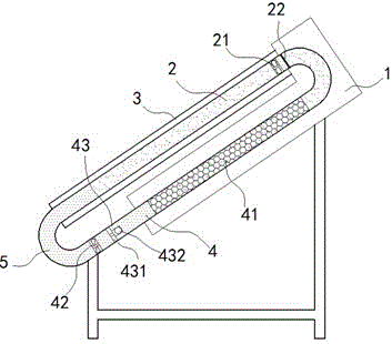
[0013] exist figure 1 In the shown embodiment, the simple air source water heater includes a bracket, a water storage tank 1 and a heat absorption pipe 2; the surface of the heat absorption pipe 2 is coated with a heat absorption coating; The coaxial sleeve is provided with a transparent tube 3, and the transparent tube 3 is fixed on the water storage tank 1; the space between the transparent tube 3 and the heat-absorbing tube 2 is vacuumized; The upper end stretches into the inside of the water storage tank 1 and communicates with the cooling pipe 4 located inside the water storage tank 1. The cooling pipe 4 is filled with mesh-shaped liquefied cotton 41; the lower end of the cooling pipe 4 extends out of the storage tank. Water tank 1, the lower end of the cooling pipe 4 is airtightly connected with the lower end of the heat absorption pipe 2 through a return pipe 5; the heat absorption pipe 2 and the cooling pipe 4 are filled with cooling liquid; the heat absorption pipe 2 ...


PUM


Abstract

The invention relates to a simple air source water heater. The simple air source water heater comprises a support, a water storage tank and a heat absorbing tube. The upper end of the heat absorbing tube extends into the water storage tank and communicates with a cooling tube located in the water storage tank. The lower end of the cooling tube extends out of the water storage tank and is in airtight connection with the lower end of the heat absorbing tube through a return pipe. The heat absorbing tube and the cooling tube are filled with cooling liquid. A suction fan is further installed in the upper end of the heat absorbing tube and electrically connected with a control motor. A water suction wheel is further fixedly installed at the lower end of the cooling tube and electrically connected with the control motor. A one-way valve is further fixedly installed above the water suction wheel and only allows the cooling liquid to be discharged downwards from the cooling tube. The water heater is simple in structure, convenient to install and capable of effectively improving the heating efficiency and meanwhile has the advantages of saving energy, being stable and the like.

Description

technical field [0001] The invention relates to a solar water heater, especially an air source water heater. Background technique [0002] A water heater is a tool that provides hot water for a limited range. After years of development, water heaters are divided into the following categories: storage electric water heaters, instant electric water heaters, instant electric water heaters, gas water heaters, solar electric water heaters and air Among them, the air source water heater is favored by the majority of users due to its advantages of stability, high efficiency, and energy saving; After heating, the functions of temperature rise and circulation are realized. This kind of water heater only performs energy transfer rather than energy conversion during the working process, so it requires less electric energy and is more energy-saving in terms of electricity consumption; however, the structure of this kind of water heater is more complicated. The production cost is rela...

Claims


Application Information

Patent Timeline
IPC IPC(8): F24J2/32F24S10/95
CPCY02E10/44
Inventor 胡振华
Owner 胡振华
Learn More