A vacuum injection device

A vacuum injection device and vacuum pumping technology, which are applied in the manufacture of hybrid/electric double layer capacitors, sustainable manufacturing/processing, climate sustainability, etc. Expensive and other problems, to achieve precise control of injection volume, good infiltration effect, and good injection effect.

Active Publication Date: 2018-04-24
SUZHOU INST OF NANO TECH & NANO BIONICS CHINESE ACEDEMY OF SCI
View PDF7 Cites 0 Cited by
  • Summary
  • Abstract
  • Description
  • Claims
  • Application Information

AI Technical Summary

Problems solved by technology

[0007] (1) The vacuum liquid injection device has a complex structure and a large volume
The operation and control of this type of vacuum liquid injection device are often cumbersome, and the equipment is expensive
In addition, its huge volume cannot be used to inject liquid into smaller button batteries
[0008] (2) The effect of directly dropping the electrolyte is not good
However, for thick electrode sheets, this natural wetting method is not enough to achieve complete infiltration of the electrolyte on the thick electrode sheet
[0009] (3) It is difficult to control the accuracy of the injection volume, and the injection speed is slow
Existing vacuum liquid injection devices often cannot accurately control the liquid injection volume, or affect the liquid injection speed in order to adjust the liquid injection volume. quality
[0010] (4) When injecting different electrolytes, it is easy to produce cross-contamination
In the process of battery research and development, it is often necessary to inject different electrolytes into the electrode sheet to test the effect. The liquid injection parts in the existing vacuum liquid injection device are often fixed, difficult to replace, or the replacement cost is high, so Using the same liquid injection parts to inject different electrolytes will inevitably bring about the problem of cross contamination

Method used


Image

  • A vacuum injection device
  • A vacuum injection device
  • A vacuum injection device

Examples


Embodiment 1

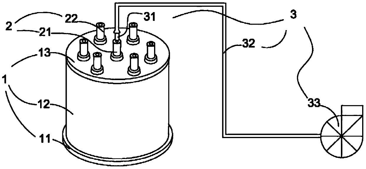
[0049] refer to Figure 1 to Figure 2 , the present embodiment provides a vacuum liquid injection device, including a vacuum chamber 1, a flexible joint 2, a vacuum member 3 and a syringe (not shown) with electrolyte, the vacuum chamber 1 is composed of a base 11, a side wall 12 and the top cover 13 are enclosed, and the corrugated joint 2 is arranged in the top cover 13 of the vacuum chamber 1, and is used to connect the vacuum pumping component 3 and the syringe containing the electrolyte to the vacuum chamber 1 respectively.

[0050] The vacuum chamber 1 is a cylindrical chamber, the base 11 is a circular base with a diameter of 105 mm, the height of the side wall 12 is 80 mm, and the top cover 13 is a circular top cover with a diameter of 95 mm. There are seven openings for inserting the Clifford joint 2.

[0051] Six battery slots 14 and a groove 15 are arranged in the base 11. The battery slots 14 are battery slots for button batteries with a diameter of 20.5mm. The dia...

Embodiment 2

[0063] The difference between this embodiment and Embodiment 1 lies in the size of the vacuum chamber.

[0064] In this embodiment, the vacuum chamber 1 is a cylindrical chamber, the base 11 is a circular base with a diameter of 80 mm, the height of the side wall 12 is 50 mm, and the top cover 13 is a circular top cover with a diameter of 70 mm.

Embodiment 3

[0066] The difference between this embodiment and Embodiment 1 lies in the size of the vacuum chamber.

[0067] In this embodiment, the vacuum chamber 1 is a cylindrical chamber, the base 11 is a circular base with a diameter of 120 mm, the height of the side wall 12 is 100 mm, and the top cover 13 is a circular top cover with a diameter of 110 mm.


PUM

PropertyMeasurementUnit
diameteraaaaaaaaaa
heightaaaaaaaaaa
diameteraaaaaaaaaa

Abstract

The invention relates to a vacuum liquid injection device, which comprises a vacuum chamber, a Clifford joint, a vacuum pumping part and a syringe filled with an electrolyte. Inserted in the opening of the top cover, the vacuum pumping part includes a connecting pipe, a hose and a vacuum pump, and the two ends of the hose are respectively connected to the vacuum pump and the connecting pipe, and the open joint includes the first connecting pipe and the vacuum chamber. A claf joint and a second claf joint for connecting the syringe containing the electrolyte to the vacuum chamber. The Clifford connector of the present invention includes a shell, a sealing cover and a connecting conduit, has good airtightness, and can cooperate with a vacuum pumping component and a syringe filled with electrolyte to realize vacuum pumping and liquid injection functions. The vacuum liquid injection device of the present invention has the advantages of simple structure, small volume, good liquid injection effect, precise liquid injection volume, fast liquid injection speed and comprehensive beneficial effects such as meeting the injection requirements of different electrolytes.

Description

technical field [0001] The invention relates to the field of battery production equipment, in particular to a vacuum liquid injection device for batteries. Background technique [0002] With the rapid development of communication technology and intelligent systems, people have higher and higher demands for energy storage of batteries or supercapacitors in various devices, such as mobile phones, notebook computers or handheld computers. [0003] In practical applications, both button batteries and supercapacitors are gradually developing toward the use of thick electrode sheets. By using thick electrode sheets, the areal density of active materials on the electrode sheets is increased, thereby improving energy storage capacity. However, the use of thick electrode sheets will inevitably face the problem of insufficient wetting of the electrolyte in the thick electrode sheets, which makes it difficult for the active materials in the electrodes to be effectively utilized, and th...

Claims


Application Information

Patent Timeline
Patent Type & Authority Patents(China)
IPC IPC(8): H01M10/04H01G11/84
CPCY02E60/10Y02P70/50
Inventor 王可杜兆龙马万顺卢威陈立桅
Owner SUZHOU INST OF NANO TECH & NANO BIONICS CHINESE ACEDEMY OF SCI
Why Eureka
Try Eureka