
Built-in permanent-magnet synchronous motor

A permanent magnet synchronous motor technology, applied to synchronous motors with stationary armatures and rotating magnets, synchronous machines, synchronous machine parts, etc., to achieve the effects of improving performance, reducing torque ripple, and improving the effect of magnetic concentration

Active Publication Date: 2016-05-11
SOUTHEAST UNIV
View PDF5 Cites 3 Cited by
  • Summary
  • Abstract
  • Description
  • Claims
  • Application Information

AI Technical Summary

Problems solved by technology

[0004] Technical problem: The technical problem to be solved by the present invention is: to provide a built-in permanent magnet synchronous motor, which solves the problem that the traditional magnetic barrier design reduces torque ripple without increasing output torque and improves single performance; through multi-layer combination The magnetic barrier not only improves the air gap magnetic density distribution and reduces torque ripple, but also improves the torque output capability, and finally improves the torque comprehensive performance of the built-in permanent magnet synchronous motor

Method used


Image

  • Built-in permanent-magnet synchronous motor
  • Built-in permanent-magnet synchronous motor
  • Built-in permanent-magnet synchronous motor

Examples


Embodiment Construction

[0020] The embodiments of the present invention will be further explained below in conjunction with the accompanying drawings.

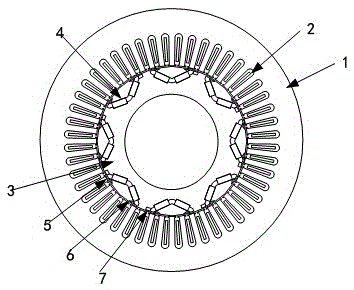
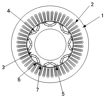
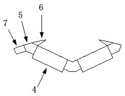
[0021] Such as figure 1 and image 3 As shown, an interior permanent magnet synchronous motor according to an embodiment of the present invention includes a stator 1 , an armature winding 2 and a rotor 3 . The armature winding 2 is wound on the teeth of the stator 1 in a distributed manner, and the rotor 3 is located in the cavity of the stator 1; the rotor 3 is provided with a V-shaped permanent magnet 4 arranged along the circumference of the rotor 3, and the two ends of the permanent magnet 4 towards stator 1. In each permanent magnet 4 , first magnetic barriers 5 are provided at both ends of the permanent magnet 4 , and a magnetic barrier group is provided outside and inside the permanent magnet 4 .

[0022] As a preferred example, each of the magnetic barrier groups includes two second magnetic barriers 6 and a third magnetic barrier 7, the t...


PUM


Abstract

The invention discloses a built-in permanent-magnet synchronous motor, which comprises a stator, an armature winding and a rotor, wherein the armature winding is wound on teeth of the stator in a distributed manner; the rotor is located in a hollow cavity of the stator; V-shaped permanent magnets which are distributed along the circumferential direction of the rotor are arranged on the rotor; two ends of the permanent magnets are toward the stator; and in each permanent magnet, first magnetic barriers are arranged at two ends of the permanent magnet and magnetic barrier groups are arranged at the outer side and the inner side of the permanent magnet respectively. The built-in permanent-magnet synchronous motor solves the problems that a traditional magnetic barrier design reduces torque ripples, does not improve an output torque and only improves the performance; through multi-layer combined magnetic barriers, air-gap magnetic density distribution is improved; the torque ripples are reduced; meanwhile, the torque output capability is also improved; and the torque comprehensive performance of the built-in permanent-magnet synchronous motor is finally improved.

Description

technical field [0001] The invention belongs to the field of permanent magnet motors, and in particular relates to a built-in permanent magnet synchronous motor. Background technique [0002] The built-in permanent magnet synchronous motor has the advantages of high power density, strong torque output capability, wide speed range and high efficiency, and has been widely used in the field of electric vehicle drive, such as commercial hybrid electric vehicles such as Prius. However, the large torque ripple of the built-in permanent magnet synchronous motor is still a problem to be solved. The torque ripple affects the loss, noise and vibration of the motor during operation, thereby affecting the efficiency of electric vehicles and the comfort of riding. Therefore, improving torque ripple and reducing losses are the current research hotspots of interior permanent magnet synchronous motors. [0003] In order to solve the torque quality problem of the traditional built-in perman...

Claims


Application Information

Patent Timeline
IPC IPC(8): H02K21/14H02K21/02
CPCH02K21/029H02K21/145
Inventor 樊英谭超陈斯雨
Owner SOUTHEAST UNIV
Learn More