Dynamic measurement system for blade tip clearance

A blade tip clearance and dynamic measurement technology, which is applied in the direction of measuring devices, instruments, and electrical devices, to achieve the effects of reducing interference, improving test efficiency, and compact overall structure

Inactive Publication Date: 2016-05-18
AECC SHENYANG ENGINE RES INST
View PDF7 Cites 20 Cited by
  • Summary
  • Abstract
  • Description
  • Claims
  • Application Information

AI Technical Summary

Problems solved by technology

[0005] The purpose of the present invention is to provide a dynamic measurement system for blade tip clearance to solve at least one problem in the background technology

Method used


Image

  • Dynamic measurement system for blade tip clearance
  • Dynamic measurement system for blade tip clearance
  • Dynamic measurement system for blade tip clearance

Examples


Embodiment Construction

[0017] In order to make the objectives, technical solutions and advantages of the present invention clearer, the technical solutions in the embodiments of the present invention will be described in more detail below in conjunction with the drawings in the embodiments of the present invention. In the drawings, the same or similar reference numerals denote the same or similar elements or elements having the same or similar functions throughout. The described embodiments are some, but not all, embodiments of the invention. The embodiments described below by referring to the figures are exemplary and are intended to explain the present invention and should not be construed as limiting the present invention. Based on the embodiments of the present invention, all other embodiments obtained by persons of ordinary skill in the art without creative efforts fall within the protection scope of the present invention. Embodiments of the present invention will be described in detail below ...


PUM


Abstract

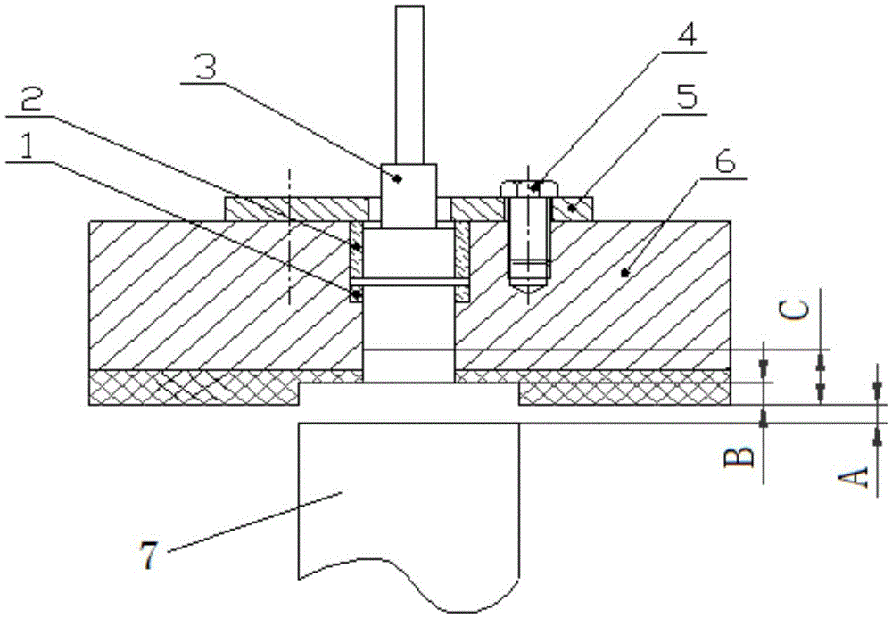
The invention discloses a dynamic measurement system for the blade tip clearance and relates to the technical field of engines. The dynamic measurement system for the blade tip clearance comprises a capacitive sensor and a capacitive sensor signal-processing structure. The capacitance sensor is arranged on the casing of an engine. The induction terminal of the capacitive sensor is lower than the inner surface of the casing of the engine. A to-be-measured blade tip clearance is formed between the inner surface of the casing of the engine and a blade tip. The rotor of the engine is in normal operation. The to-be-measured blade tip clearance is dynamically changing. The capacitive sensor transmits an induction signal to the capacitive sensor signal-processing structure. The capacitive sensor signal-processing structure is used for processing the signal transmitted from the capacitive sensor. The system is simple and compact in structure, and the measurement of the system is realized in the non-contact mode. Therefore, the interference of the system on the jet flow field of the engine is reduced. The requirement of the on-line dynamic measurement on the blade tip clearance of the engine can be met.

Description

technical field [0001] The invention relates to the technical field of engines, in particular to a dynamic measurement system for blade tip clearance. Background technique [0002] Aeroengine tip clearance refers to the radial distance between the tip of the rotor blade and the inner wall of the casing or the inner surface of the coating. The optimal design of the tip clearance has a great influence on the working efficiency and structural safety of the compressor and turbine, especially the last stages of the high-pressure compressor and the high-pressure turbine. At present, with the increasing maturity of compressor and turbine design technology, the design of optimal tip clearance, active clearance control and blade health monitoring have become the focus of the work of researchers at home and abroad, and the above research process is inseparable from the rotor blade. Dynamic testing technology for blade tip clearance. [0003] Since the 1980s, engineers at home and ab...

Claims


Application Information

Patent Timeline
Patent Type & Authority Applications(China)
IPC IPC(8): G01B7/14
CPCG01B7/14
Inventor 韩鹏卓张龙黄瑛刘忠奎薛秀生
Owner AECC SHENYANG ENGINE RES INST
Why Eureka
Try Eureka