
Systolic structure matrix multiplier based on FPGA (Field Programmable Gate Array) and implementation method thereof

A technology of structure matrix and implementation method, which is applied in the direction of instruments, electrical digital data processing, and digital data processing components, etc., can solve the problems of high fan-out of matrix multiplier input modules, difficulty in achieving overall performance, and complex data input control. Achieve the effect of reducing overall power consumption, convenient reconfiguration, and low power consumption performance

Inactive Publication Date: 2016-05-18
SHENYANG GOLDING NC & INTELLIGENCE TECH CO LTD
View PDF4 Cites 25 Cited by
  • Summary
  • Abstract
  • Description
  • Claims
  • Application Information

AI Technical Summary

Problems solved by technology

[0007] Aiming at the above-mentioned deficiencies in the prior art, the technical problem to be solved by the present invention is to provide a method that can solve the problem that the fan-out of the input module of the existing matrix multiplier is too high, it is difficult to achieve high overall performance, the data input control is complex, and the calculation The final result is difficult to read, and the whole is not modular, and most of the modifications are needed after transplantation. An FPGA-based pulsating structure matrix multiplier and its implementation method

Method used


Image

  • Systolic structure matrix multiplier based on FPGA (Field Programmable Gate Array) and implementation method thereof
  • Systolic structure matrix multiplier based on FPGA (Field Programmable Gate Array) and implementation method thereof
  • Systolic structure matrix multiplier based on FPGA (Field Programmable Gate Array) and implementation method thereof

Examples


Embodiment Construction

[0041] The present invention will be further described in detail below in conjunction with the accompanying drawings and embodiments.

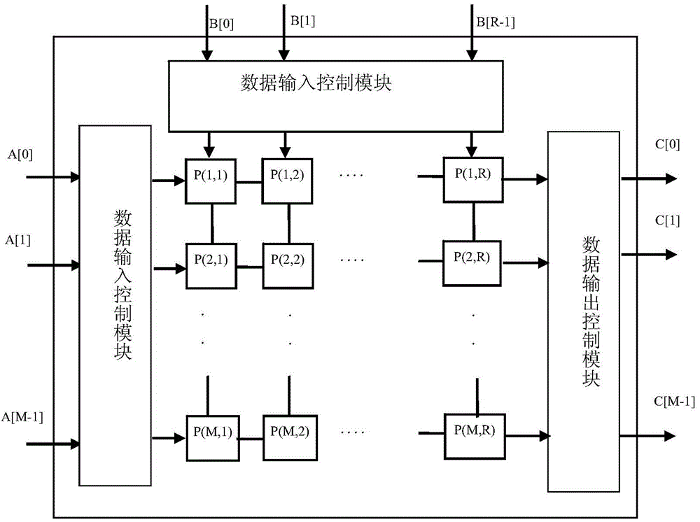
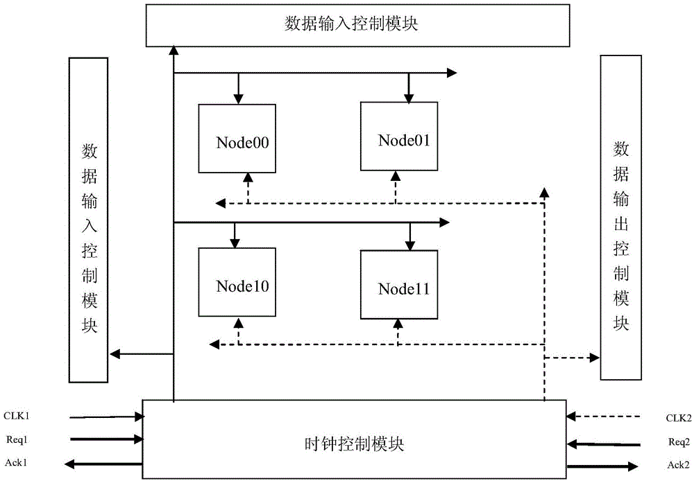
[0042] Such as figure 2Shown, a kind of pulsating structure matrix multiplier based on FPGA comprises: multiplier array, clock control module, data input control module, data output control module; Described multiplier array is the two-dimensional mesh array structure of M row R row , consisting of M×R node units, and adjacent node units are interconnected to realize the product operation of the input matrix A and matrix B; the clock control module is used to output two clocks, which are respectively provided to the data input A control module and a data output control module; the data input control module is used to input matrix A and matrix B in parallel under the control of the clock control module, wherein matrix A is M rows and N columns, and matrix B is N rows and R columns; The data output control module is used to output matrix C, wh...


PUM


Abstract

The invention provides a systolic structure matrix multiplier based on an FPGA (Field Programmable Gate Array) and an implementation method thereof. The systolic structure matrix multiplier comprises a multiplier array composed of M x R node units, a clock control module, a data input control module and a data output control module; the M x R node units are interconnected by a two-dimensional mesh array structure of M rows and R columns, used for performing a multiply-accumulate calculation on data, and have systolic structures in each data direction of rows and columns; the clock control module is used for providing a clock, controlling the whole calculation process, and recoding the state of a current multiplier; the data input control module is used for controlling an input matrix to input by rows or by columns, and making the input matrix to satisfy an input rule of time alignment; and the data output control module is used for outputting the calculation results by rows or by columns under the control of an output clock. The implementation method of the matrix multiplier provided by the invention can enable data to enter the matrix multiplier according to the input rule of the systolic structure by rows or by columns, and perform a multiply-add operation and output the calculation results. The systolic structure matrix multiplier based on the FPGA provided by the invention has the advantages of being very high in calculation performance, good in modularity and convenient in reconfiguration.

Description

technical field [0001] The invention relates to the field of FPGA technology and high-performance computing technology, in particular to an FPGA-based systolic matrix multiplier and an implementation method thereof. Background technique [0002] Matrix multiplication is widely used as a basic operation in scientific computing, digital signal processing, etc., and its computing performance directly affects the overall performance of the system. Gradually become the bottleneck of system computing performance. [0003] Previous matrix multiplication operations usually use hardware as a general-purpose processor and software to implement matrix multiplication, or use hardware as a dedicated digital signal processor (Digital Signal Process, DSP) to achieve. This type of processing method is relatively mature in technology, complete in implementation tools, and simple in programming. However, due to its internal structure and platform limitations, it is not suitable for occasions...

Claims


Application Information

Patent Timeline
IPC IPC(8): G06F7/523
Inventor 陶耀东周磊涛李锁齐济
Owner SHENYANG GOLDING NC & INTELLIGENCE TECH CO LTD
Learn More