
Connections for friction clutches and torsional vibration dampers

A friction clutch and torsional vibration technology, applied in clutches, fluid-driven clutches, mechanical-driven clutches, etc., can solve the problems of structural failure, noise, and reduce the unevenness of internal combustion engine rotation, and achieve improved vibration reduction and small axial installation effect of space

Active Publication Date: 2020-05-05
SCHAEFFLER TECH AG & CO KG
View PDF13 Cites 0 Cited by
  • Summary
  • Abstract
  • Description
  • Claims
  • Application Information

AI Technical Summary

Problems solved by technology

[0002] Although most clutch systems are suitable for the available installation space, their design does not offer the possibility of integrating other measures for reducing the rotational inhomogeneity of the internal combustion engine
In addition, the connection part has clearance due to the clutch and dual mass flywheel needing to be installed separately, which may cause noise during operation

Method used


Image

  • Connections for friction clutches and torsional vibration dampers
  • Connections for friction clutches and torsional vibration dampers
  • Connections for friction clutches and torsional vibration dampers

Examples


Embodiment Construction

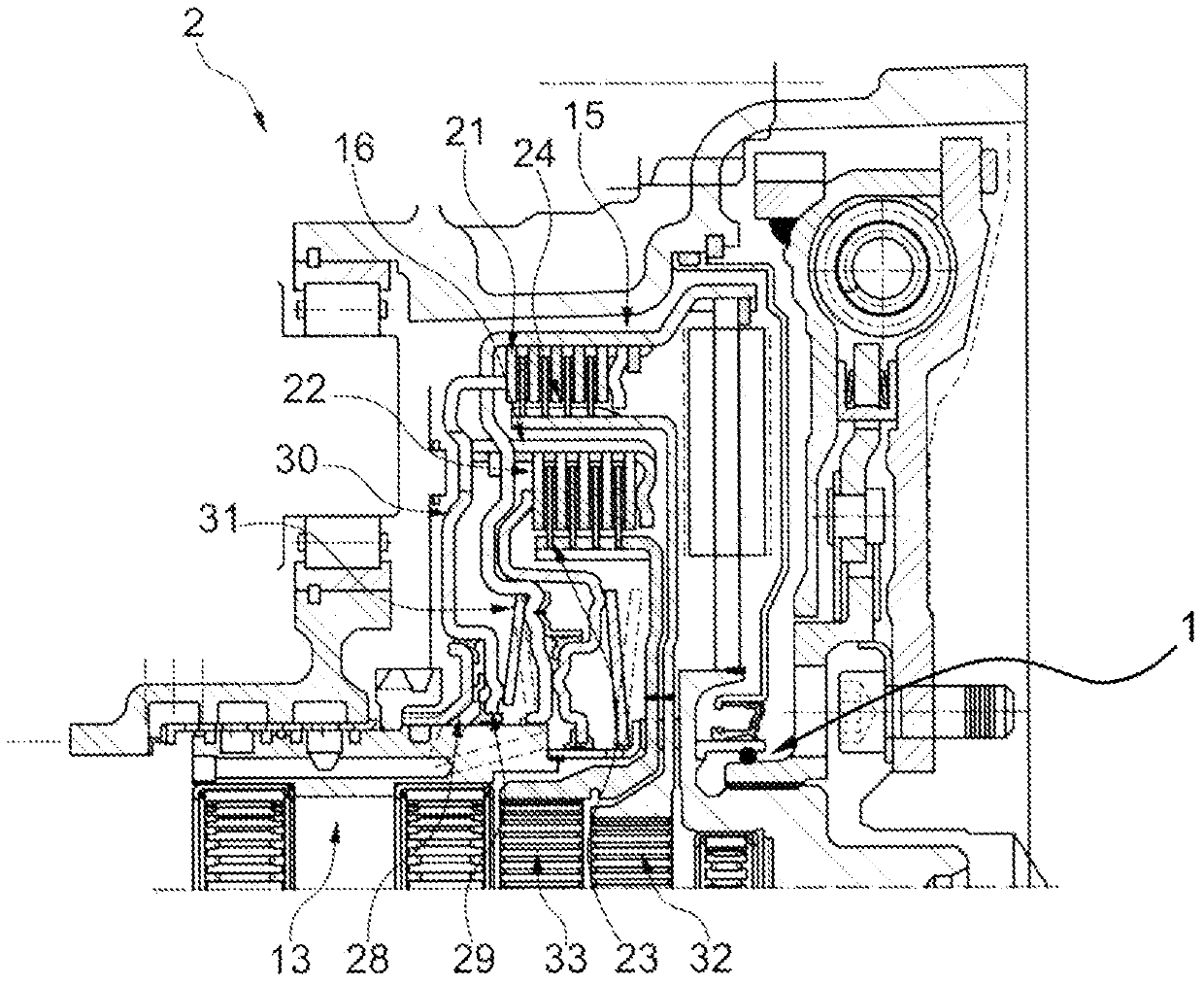
[0042] figure 1 A friction clutch 2 is shown, in which a first friction set 15 and a second friction set 16 are arranged. The first friction group 15 here comprises a first pressure plate 21 and a first friction disc 23, while the second friction group 16 comprises a second pressure plate 22 and a second friction disc 24, which can respectively form a friction locking contact with each other. , so that the torque in the friction sets 15 and 16 is switchably transmitted. In this exemplary embodiment, the friction groups 15 and 16 are actuated, for example, by means of a pressure chamber 28 , which acts on the actuation device 30 in such a way that one friction group 15 or 16 in each case is compressed. The return spring 31 here generates the counterforce required to release the friction set 15 or 16 . The torque transmitted from the driven shaft 13 can be transmitted to the first output shaft 32 or the second output shaft 33 through the friction sets 15 and 16 . Furthermore,...


PUM


Abstract

The invention relates to a connecting device for a friction clutch and a torsional vibration damper, which has at least the following parts: an output element of the torsional vibration damper; an input element of the friction clutch, which is connected by means of a plug-in connection The output element is connected in a torque-transmitting manner; the clamping element for clamping the plug-in connection without play. With the connection proposed here, a noiseless connection between friction clutch and torsional vibration damper, a simple installation procedure and a small installation space are possible.

Description

technical field [0001] The invention relates to a coupling device for friction clutches and torsional vibration dampers and can be used in many motor vehicles or commercial vehicles with gasoline or diesel engines, in which the In the case of clutch systems, a compact design as well as a high degree of comfort during operation are of great importance. Background technique [0002] Although most clutch systems are suitable for the available installation space, their design does not offer further possibilities for integrating measures for reducing the rotational inhomogeneity of the internal combustion engine. In addition, the connection part has play because the clutch and the dual-mass flywheel need to be installed separately, which may cause noise during operation. Contents of the invention [0003] Based on this, the object of the present invention is to at least partially overcome the disadvantages known from the prior art. [0004] The invention relates to a coupling...

Claims


Application Information

Patent Timeline
Patent Type & Authority Patents(China)
IPC IPC(8): F16D21/06F16D25/00
CPCF16D21/06F16D25/00F16D2021/0661F16D25/0638F16F15/1207F16D25/10
Inventor J·芬克D·霍夫施泰特尔A·阿尔默特P·泰珀
Owner SCHAEFFLER TECH AG & CO KG
Learn More