
Wet dust remover

A wet dust collector and housing technology, applied in the field of dust removal equipment, can solve the problems of poor dust and water droplet aggregation effect, affecting the stability of the dust collector, and blocked rotation of the rotating shaft, so as to improve efficiency and dust removal effect, improve dust removal effect, The effect of reducing consumption

Inactive Publication Date: 2016-05-25
YANCHENG HUAWEI CASTING MACHINERY
View PDF0 Cites 3 Cited by
  • Summary
  • Abstract
  • Description
  • Claims
  • Application Information

AI Technical Summary

Problems solved by technology

[0003] The industrial dust collector in the prior art includes a housing, a spray mechanism and a motor. The fan of the dust collector is installed at the air inlet, and the air with dust will pass through the fan. After a period of use, the fan may be damaged due to too much dust. As a result, the rotation of the rotating shaft is blocked, and when the situation is serious, the motor in the fan will be burned. At the same time, the water sprayed by the spray mechanism of the dust collector in the prior art cannot enter various parts of the housing, so that the condensation effect of dust and water droplets is not good. , which affects the stability of the dust collector

Method used


Image

  • Wet dust remover

Examples


Embodiment 1

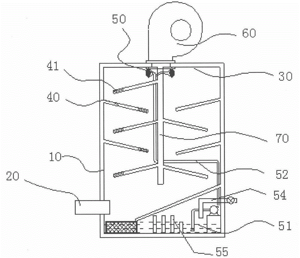
[0015] The wet dust collector disclosed in the present invention includes a hollow cylindrical shell 10, an air inlet 20, a partition 40 inclined downward, an air outlet 30, a sedimentation tank, a reservoir 51, and a water inlet pipe connected to the reservoir 51 54. The diversion plate and the spray assembly, the sedimentation tank and the reservoir 51 are respectively arranged on both sides of the housing 10, the diversion plate is inclined downward from the top of the reservoir 51 to the direction of the sedimentation tank, and the spray assembly includes a nozzle 50, a water pump As well as the duct 52, the air inlet 20 is arranged on the lower side wall of the housing 10 and the centerline of the air inlet 20 is along the tangential direction of the housing 10, and a number of guide flow holes are also opened on the partition 40, and the air outlet 30 is arranged on the housing 10. The top and the center line of the air outlet 30 coincide with the axial direction of the c...

Embodiment 2

[0017] The wet dust collector disclosed in the present invention includes a hollow cylindrical shell 10, an air inlet 20, a partition 40 inclined downward, an air outlet 30, a sedimentation tank, a reservoir 51, and a water inlet pipe connected to the reservoir 51 54. The diversion plate is provided with a baffle plate 70 with a through hole and a spray assembly. The baffle plate 70 is vertically arranged in the housing 10, and the sedimentation tank and the water storage tank 51 are respectively arranged on both sides of the housing 10. The drainage plate Inclined downward from the top of the reservoir 51 towards the sedimentation tank, the spray assembly includes a nozzle 50, a water pump and a conduit 52, the air inlet 20 is arranged on the lower side wall of the housing 10 and the centerline of the air inlet 20 is along the tangential direction of the housing 10, A plurality of guide holes are also opened on the partition 40 , the air outlet 30 is arranged on the top of the...

Embodiment 3

[0019] The wet dust collector disclosed in the present invention includes a hollow cylindrical shell 10, an air inlet 20, a partition 40 inclined downward, an air outlet 30, a sedimentation tank, a reservoir 51, and a water inlet pipe connected to the reservoir 51 54. A diversion plate, an exhaust fan 60, a baffle plate 70 with a through hole and a spray assembly, the baffle plate 70 is vertically arranged in the housing 10, and the sedimentation tank and the water storage tank 51 are respectively arranged on two sides in the housing 10. side, the diversion plate is inclined downward from the top of the reservoir 51 to the direction of the sedimentation tank, the spray assembly includes a nozzle 50, a water pump and a conduit 52, the air inlet 20 is arranged on the lower side wall of the housing 10 and the centerline of the air inlet 20 is along the In the tangential direction of 10, a number of guiding holes are opened on the partition 40. The air outlet 30 is arranged on the ...


PUM


Abstract

The present invention discloses a wet dust remover, which comprises a hollow cylindrical housing, a wind inlet, downwardly-inclining separation plates, a wind outlet, a sedimentation pool, a water storage pool, a water inlet pipe communicated to the water storage pool, a draining plate and a spraying assembly, wherein the sedimentation pool and the water storage pool are respectively arranged on both sides inside the housing, the draining plate downwardly inclines from the direction above the water storage pool to the sedimentation pool direction, the spraying assembly comprises spraying nozzles, the water storage pool, a water pump and a conducting pipe, the wind inlet is arranged on the side wall of the lower portion of the housing, the center line of the wind inlet is along the housing tangent line direction, the separation plates are provided with a plurality of draining through holes, the wind outlet is arranged on the top portion of the housing, and the center line of the wind outlet axially coincides with the housing. According to the present invention, the wet dust remover has the simple structure, the tangential wind inlet way is used, and the water leaching is used to remove the dust while the frictional resistance viscosity effect of the side wall of the housing is utilized, such that the advantages of good dust removing effect, high efficiency, low water consumption and stable use are provided.

Description

technical field [0001] The invention belongs to the technical field of dust removal equipment and relates to a wet dust collector. Background technique [0002] In the process of industrial production, some workplaces will produce a lot of dust, which needs to be treated by a dust removal device before being discharged into the outside world, otherwise it will cause harm to the environment. [0003] The industrial dust collector in the prior art includes a housing, a spray mechanism and a motor. The fan of the dust collector is installed at the air inlet, and the air with dust will pass through the fan. After a period of use, the fan may be damaged due to too much dust. As a result, the rotation of the rotating shaft is blocked, and when the situation is serious, the motor in the fan will be burned. At the same time, the water sprayed by the spray mechanism of the dust collector in the prior art cannot enter various parts of the housing, so that the condensation effect of du...

Claims


Application Information

Patent Timeline
IPC IPC(8): B01D50/00
Inventor 施维
Owner YANCHENG HUAWEI CASTING MACHINERY
Learn More