
Automatic tin adding electric soldering iron

An electric soldering iron and automatic technology, applied in the field of electronics, can solve the problems of liquid tin having no fluidity, poor practicability, and difficult to spray components, etc., and achieve the effects of simple and convenient use, simple internal structure, and strong practicability.

Inactive Publication Date: 2016-05-25
HUBEI UNIV OF TECH
View PDF5 Cites 15 Cited by
  • Summary
  • Abstract
  • Description
  • Claims
  • Application Information

AI Technical Summary

Problems solved by technology

Therefore, the design of the heating device is a difficult point. The patent application document CN104526101A discloses a touch-pressure automatic tin-supply soldering iron. It is pointed out that because the solder is in liquid state for a long time, all the flux in the tin wire will be sublimated. The result is that the liquid tin has no fluidity and is difficult to be sprayed on the components. Even if it can be sprayed, it has no fluidity. So poor practicality

Method used


Image

  • Automatic tin adding electric soldering iron
  • Automatic tin adding electric soldering iron
  • Automatic tin adding electric soldering iron

Examples


Embodiment Construction

[0022] Hereinafter, the present invention will be illustrated with examples in conjunction with the drawings.

[0023] The invention is composed of a transmission module and a heating module.

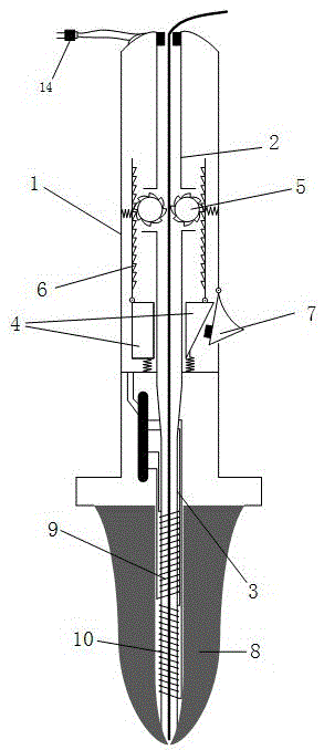
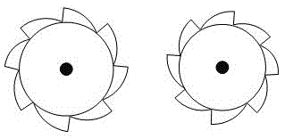
[0024] The transmission module includes a housing 1, an inner cavity 2, a pushing body 4, a round gear 5, a spur gear 6, a ceramic inner cavity 3 and a wire button 7.

[0025] The inner cavity 2 is made of ordinary plastic, connected to the entire soldering iron, and is a channel for the transmission of tin wires of different specifications. The shape is a hollow cylinder with a diameter of 6mm. Butt with the ceramic inner cavity 3 at the lower end to form an internal channel.

[0026] The shell 1 is made of heat-insulating plastic and has a hollow cylindrical shape with a diameter of 17mm. A protrusion is provided at the lower end of the shell 1 to prevent the heating element 8 from being touched by hand sliding, and the diameter of the protrusion is 28mm.

[0027] The circular gear 5 is locate...


PUM

PropertyMeasurementUnit
Depthaaaaaaaaaa

Abstract

The invention discloses an automatic tin adding electric soldering iron which comprises a transmission module and a heating module. The transmission module comprises a shell, an inner cavity, an inner ceramic cavity, a pushing body and a wire adding button, wherein the upper end of the inner ceramic cavity is sleeved with the pushing body. A pair of one-way rotation circular gears are arranged at the joint of the inner cavity and the inner ceramic cavity. The side faces of the circular gears are provided with meshed straight gears. The lower ends of the straight gears are hinged to the upper end of the pushing body. A spring is arranged at the lower end of the pushing body. One side of the pushing body is in a conical shape with the large top and the small bottom. The wire adding button is hinged to the shell. The wire adding button can just press the conical side of the pushing body when rotating so that the pushing body is made to move upwards. The heating module comprises a heating body with the lower sharp nozzle type end, a conductor winding wire, a heating wire and a control circuit board, the upper end of the heating body is connected with the shell, the conductor winding wire is arranged at the lower portion of the inner ceramic cavity, and the lower portion of the inner ceramic cavity stretches into the heating body till the tip nozzle position, a user can operate the automatic tin adding electric soldering iron with one hand, tin wires are molten during welding, and no dead tin is generated.

Description

Technical field [0001] The invention belongs to the field of electronic technology, and relates to an electric soldering iron, specifically, an automatic soldering iron. Background technique [0002] Traditional electric soldering irons are divided into internal heating type and external heating type according to the heating method. It uses heat conduction to heat the front soldering iron, and then melts the tin wire to achieve the purpose of welding. However, holding the tin in one hand and the electric soldering iron in the other hand makes it difficult to grasp the position of the components on the soldering board, especially the SMD components. On the other hand, it is not well adapted to the situation of mass manual welding. [0003] Since the melting point of the commonly used solder wire is about 200 degrees Celsius, and the solder wire is generally added with flux, the flux will increase the fluidity of the solder, but the flux will sublime when the solder is around 100 d...

Claims


Application Information

Patent Timeline
IPC IPC(8): B23K3/03B23K3/053B23K3/06
CPCB23K3/0392B23K3/053B23K3/063
Inventor 王粟徐希张威亚邱维
Owner HUBEI UNIV OF TECH
Learn More