A fixture for robot automatic welding

A technology of automatic welding and fixtures, which is applied in the field of fixtures, can solve the problems of slowing down production rhythm and long time consumption, and achieve the effect of reducing welding deformation, reducing assembly man-hours, and reducing post-welding correction deformation or repairing process.

Active Publication Date: 2017-08-29
JIANGXI HONGDU AVIATION IND GRP
View PDF5 Cites 0 Cited by
  • Summary
  • Abstract
  • Description
  • Claims
  • Application Information

AI Technical Summary

Problems solved by technology

The traditional welding tooling cannot meet the positioning accuracy of the tooling and the accuracy of the relative position of the welding seam for automatic welding. After each clamping, the clamping state of the workpiece needs to be adjusted to meet the welding requirements. This process takes a long time. Slow down the entire production rhythm

Method used


Image

  • A fixture for robot automatic welding
  • A fixture for robot automatic welding
  • A fixture for robot automatic welding

Examples


Embodiment Construction

[0022] The present invention will be further described below in conjunction with the accompanying drawings and specific embodiments. The following examples are only used to illustrate the present invention, and are not intended to limit the protection scope of the present invention.

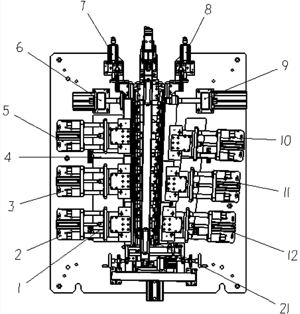
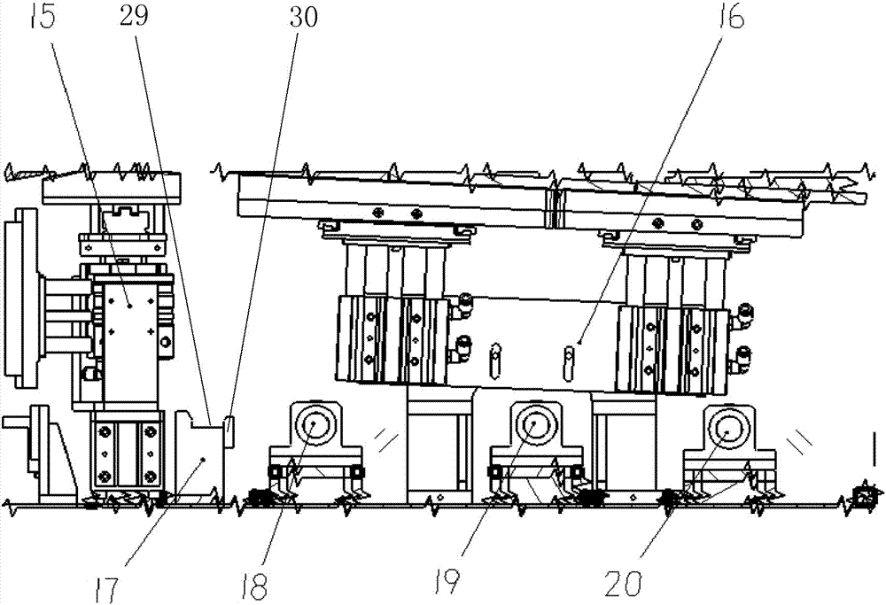
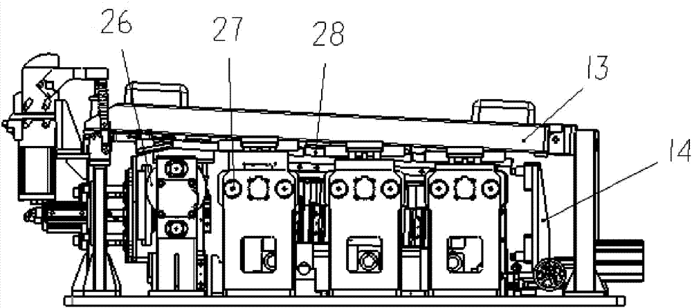
[0023] figure 1 , figure 2 and image 3 As shown, a tooling fixture for robot automatic welding of the present invention includes a diaphragm ear piece positioning assembly 14, shaft hole positioning assemblies 6, 9, flat plate pressing assemblies 2, 3, 5, curved plate pressing Components 10, 11, 12, side wall plate pressing components 7, 8, beam components 13, back air protection jacking mechanisms 15, 16, jacking and pressing mechanisms 18, 19, 20, intermediate frame assembly components 17 and auxiliary Supports 1, 4, flat panel pressing assemblies 2, 3, 5 and curved panel pressing assemblies 12, 11, 10 are respectively located on both sides of the middle of the crossbeam assembly 13, and s...


PUM


Abstract

The invention discloses a tool clamp used for robot automatic welding. The tool clamp comprises a separation plate tab positioning assembly (14), shaft hole positioning assemblies (6, 9), plane plate compression assemblies (2, 3, 5), curved plate compression assemblies (10, 11, 12), side wall plate compression assemblies (7, 8), a transverse beam assembly (13), back air protective jacking mechanisms (15, 16), jacking compression mechanisms (18, 19, 20), a middle separation frame assembling component (17) and auxiliary supports (1, 4), wherein the plane plate compression assemblies (2, 3, 5) and the curved plate compression assemblies (10, 11, 12) are located on the two sides of the middle part of the transverse beam assembly (13) respectively; the side wall plate compression assemblies (7, 8) are distributed on the two sides of the front end part of the transverse beam assembly (13); the shaft hole positioning assemblies (6, 9) are further distributed on the two sides of the front end part of the transverse beam assembly (13); and the separation plate tab positioning assembly (14) is distributed at the tail part of the transverse beam assembly (13). The invention provides an automatic welding tool which is simple to operate and efficient, aiming at certain complicated thin-wall welding parts; and the requirements on tool positioning precision and clamping efficiency by robot automatic welding are met.

Description

technical field [0001] The invention relates to a tooling fixture, in particular to a tooling fixture for robot automatic welding of a complex thin-walled weldment. Background technique [0002] A complex thin-walled weldment is composed of a curved plate, a flat plate, a tail frame, a middle frame, and a cover plate. In the production process, it is necessary to use fixtures to fix the components of the weldment, and then weld the tail frame, curved panel and panel. The traditional welding tooling cannot meet the positioning accuracy of the tooling and the accuracy of the relative position of the welding seam for automatic welding. After each clamping, the clamping state of the workpiece needs to be adjusted to meet the welding requirements. This process takes a long time. Slow down the entire production rhythm. [0003] Therefore, it is necessary to provide a new technical solution to solve the above problems. Contents of the invention [0004] The technical problem t...

Claims


Application Information

Patent Timeline
Patent Type & Authority Patents(China)
IPC IPC(8): B23K37/04
CPCB23K37/04B23K37/0443
Inventor 王丽峰肖熙陈鸣晖涂慧婕余刚刘川宋蓓万里鹏袁磊汪琦原鹏飞朱裕谱
Owner JIANGXI HONGDU AVIATION IND GRP
Why Eureka
Try Eureka