Assembling device for micron-size axle and hole

An assembly device and micron-level technology, which is applied in the direction of photographic devices, assembly machines, metal processing equipment, etc., can solve the problem of not being able to realize the bonding of micro-shafts and micro-holes, and cannot meet the needs of visual observation of micron-level shaft and hole space assembly, Problems such as the inability to realize the detection of spatial relative poses

Inactive Publication Date: 2016-05-25
LASER FUSION RES CENT CHINA ACAD OF ENG PHYSICS
View PDF7 Cites 13 Cited by
  • Summary
  • Abstract
  • Description
  • Claims
  • Application Information

AI Technical Summary

Problems solved by technology

However, the three-way orthogonal microscopic vision system in this system cannot realize the detection of the spatial relative pose of the micro-axis and the micro-hole during the docking process of the micro-scale, and cannot realize the bonding of the micro-axis and the micro-hole
[0005] It can be seen that although some research progress has been made in the space assembly of tiny parts, the structure of the visual observation device of the developed system is relatively simple, which cannot meet the visual observation requirements of the micron-level shaft and hole space assembly, and cannot achieve micron Bonding of stage shafts to holes

Method used


Image

  • Assembling device for micron-size axle and hole
  • Assembling device for micron-size axle and hole

Examples


Embodiment 1

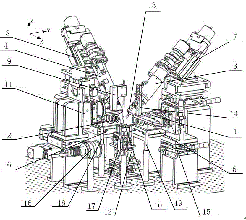
[0043] In the embodiment, the micro vision component I1, the micro vision component II2, the micro vision component III3, and the micro vision component IV4 are all composed of the TXG50C camera of the Swiss company Baumer and the variable magnification microscope lens of the American Navitar company. The magnifications of micro vision unit Ⅰ1 and micro vision unit Ⅱ2 are 1.74~21, and the magnifications of micro vision unit Ⅲ3 and micro vision unit Ⅳ4 are 5.54~66.63. The angle between the optical axes of the micro vision component III3 and the micro vision component I1 is 60°, and the angle between the optical axes of the micro vision component IV4 and the micro vision component II2 is 60°. Both the microvision position adjustment mechanism I5 and the microvision position adjustment mechanism II6 include a one-dimensional electric position adjuster along the optical axis direction, which are respectively used for the microvision component I1 and the microvision component II2 al...

Embodiment 2

[0068] The implementation of embodiment 2 is basically the same as that of embodiment 1, the main difference is that the angle between the optical axes of the micro vision component III3 and the micro vision component I1 is 45°, and the optical axis of the micro vision component IV4 and the micro vision component II2 The included axis angle is 45°. The micro-shaft at the end of the micro-shaft part and the micro-hole at the top of the micro-hole part are clearance fit, and the range of the fit clearance is 0.5 μm.

Embodiment 3

[0070] The implementation of embodiment 3 is basically the same as that of embodiment 1, the main difference is that the angle between the optical axes of the micro vision component III3 and the micro vision component I1 is 70°, and the optical axis of the micro vision component IV4 and the micro vision component II2 The included axis angle is 70°. The micro-shaft at the end of the micro-shaft part and the micro-hole at the top of the micro-hole part have a clearance fit, and the range of the fit clearance is 1.5 μm.


PUM


Abstract

The invention provides an assembling device for a micron-size axle and hole. The assembling device is used for butt-jointing and gluing a micron axle with a micron hole and comprises a control host computer, an operating platform, a position adjusting device, a multi-dimensional microscopic vision observing device and a microdot gluing device, wherein the multi-dimensional microscopic vision observing device comprises four vision observing components; two vision observing components, which are located on the horizontal plane and are orthogonally arrayed, are in lower magnification times and used for performing low-precision detection on the space positions of a micron-axle part and a micron-hole part; two vision observing components, which are crossed with the horizontal plane and are in higher magnification times, are used for performing high-precision detection on the space positions of the micron-axle at the tail end of the micron-axle part and the micron-hole at the top of the micron-hole part; the microdot gluing device is used for gluing the micron-axle with the micron-hole. The assembling device for the micron-size axle and hole can be used for realizing the high-precision assembling for the micron-size axle and hole.

Description

technical field [0001] The invention belongs to the technical field of micro-assembly, and in particular relates to an assembly device for a micron-level shaft and a hole. Background technique [0002] With the development of micro-electro-mechanical systems, higher requirements are put forward for the assembly of tiny parts. The micro-assembly robot system based on microscopic vision guidance provides an effective solution for the spatial assembly of tiny parts. [0003] A micro-manipulation robot for the assembly of tiny parts developed by Harbin Institute of Technology (Chen Liguo, Sun Lining, Rong Weibin. A micro-manipulation robot based on micro-vision and micro-force sense compliant control, High Technology Communication, 2003, 13(12): 53 -56.), using a combination of macro and micro structures to obtain a larger operating range and higher operating accuracy. The left hand is composed of a macro-motion worktable, a micro-manipulator, and a micro-gripper. The workbenc...

Claims


Application Information

Patent Timeline
Patent Type & Authority Applications(China)
IPC IPC(8): B23P21/00G01C11/02
CPCB23P21/00G01C11/02
Inventor 张娟吴文荣毕列杨宏刚王红莲温明彭博魏红
Owner LASER FUSION RES CENT CHINA ACAD OF ENG PHYSICS
Why Eureka
Try Eureka