AI technical title is built by Patsnap AI team. It summarizes the technical point description of the patent document.
一种磨削、电动的技术,应用在电动组件、磨削/抛光设备、磨床等方向,能够解决小孩子难自己操作等问题
Active Publication Date: 2016-05-25
胡建坤
View PDF10 Cites 12 Cited by
Summary
Abstract
Description
Claims
Application Information
AI Technical Summary
This helps you quickly interpret patents by identifying the three key elements:
Problems solved by technology
Method used
Benefits of technology
Problems solved by technology
There are also existing nail scissors, which are difficult for children to operate by themselves
Method used
Image
Click on the blue label to locate the original text in one second.
Reading with bidirectional positioning of images and text.
Examples
Embodiment 1
[0042] The first embodiment provides an electric grinder for cleaning the body surface of a living body.
[0043] The organisms referred to here include human body and animals, and the human body will be used as an object for description below.
[0044] The electric sonic cleansing hair brush includes a swing motor and a grinding head, the swing motor can output a reciprocating swing motion, and the grinding head swings driven by the swing motor.
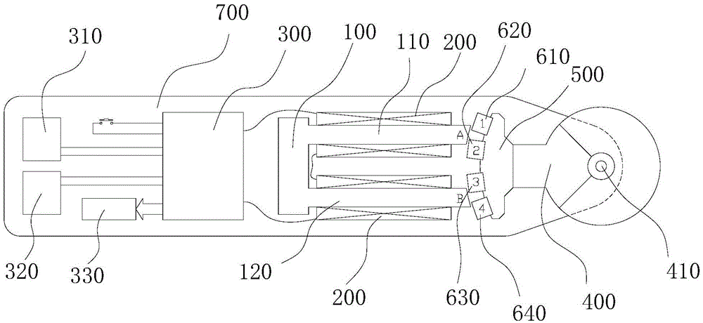
[0045] Please refer to figure 1 , 2 , 3, 4, 5, the swing motor includes:
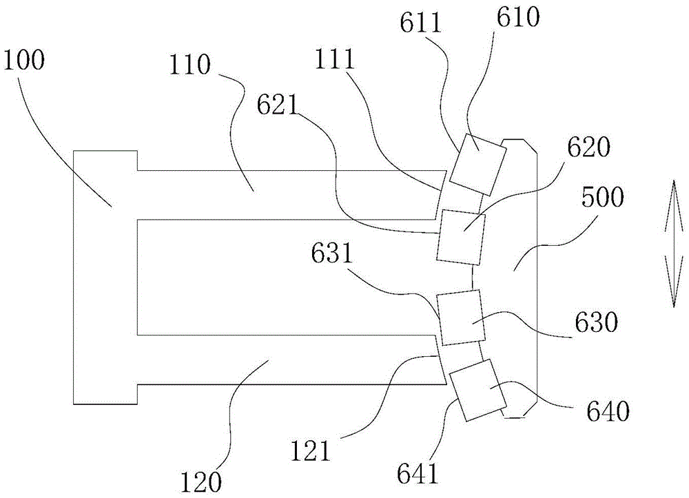
[0046] A U-shaped yoke 100, the U-shaped yoke 100 has a first leg 110 and a second leg 120, coils 200 are respectively wound on the first leg 110 and the second leg 120;
[0047] A control circuit 300, the control circuit 300 is electrically connected to the coil 200, and generates alternating pulses, so that the end faces 111 and 121 of the two legs of the U-shaped magnetic yoke 100 generate alternating magnetic poles;
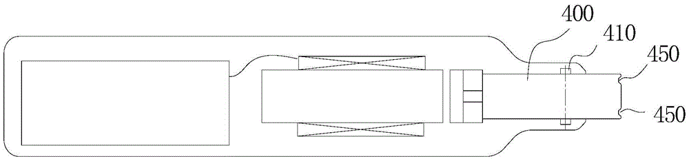
[0048]A swing arm 400 that can sw...
Embodiment 2
[0081] Embodiment 2 provides another swing motor.
[0082] Please refer to Figure 13 , the swing motor is improved on the structure shown in the first embodiment, and a resonant elastic member for generating resonance at a constant swing frequency is added.
[0083] Specifically, one end of the resonant elastic member is fixed on the fulcrum of the swing arm, and the other end is connected to the outer arm or the inner arm.
[0084] further, Figure 13 The resonant elastic member shown in is a straight spring steel wire, in addition, other shapes of elastic members can also be used instead, such as Figure 14 The middle portion of the resonant elastic member shown is curved.
Embodiment 3
[0086] The third embodiment provides another electric grinder.
[0087] Please refer to Figure 15 , 16 and 17, the electric grinder has been improved on the structure shown in Embodiment 1, and the original Figure 9 or Figure 10 Two or more clamping holes are added on the grinding head, and a second grinding head 930 can be externally connected. The second grinding head 930 can have a grinding surface 463 of a circular arc, and the cross section of the grinding surface 463 is as reference Figure 11 , used to grind the hard skin of the skin, fixed on the Figure 9 or Figure 10 on the grinding head.
[0088] Likewise, please refer to Figure 17 , The second grinding head 930 can also be provided with a sheath 922 of soft material to block the periphery of the second grinding head 930 to prevent the grinding debris from moving to the handle part.
[0089] In addition, the second grinding head 930 can also be a grinding head for grinding nails, while the original grin...
PUM
Abstract
The invention discloses an electric grinding device which comprises a swing motor and a grinding head driven by the swing motor. The swing motor comprises a U-shaped magnet yoke, four permanent magnets and a swing arm. Two supporting legs of the U-shaped magnet yoke are wound by coils. The end faces of the two supporting legs can produce alternating magnetic poles under the control of a control circuit. The four permanent magnets comprise the first permanent magnet, the second permanent magnet, the third permanent magnet and the fourth permanent magnet which are sequentially distributed on the same circle with the supporting point as the circle center. The radial end face of the first permanent magnet and that of the fourth permanent magnet are the same in polarity. The control circuit produces alternating pulses with the adjustable pulse width, and the movement direction of the permanent magnets alternately changes, so that reciprocated swing is formed, the swing arm drives the grinding head to slightly swing at a high speed in a reciprocated mode, and the body surfaces (such as skin and fingernails) of the living bodies (such as the human body and animals) are cleaned.
Description
technical field [0001] The present application relates to a cleaning tool, especially a grinder driven by a motor for grinding nails or cuticles. Background technique [0002] The motor is an electromagnetic device that realizes the conversion of electric energy according to the law of electromagnetic induction. It is widely used in various fields and is an indispensable prime mover in today's society, providing a power source for a large number of electrical appliances or various machinery. [0003] An electric grinder is a device driven by a motor, and the motor of an existing electric grinder generally uses a rotary motor. A rotating electrical machine is a rotating electromagnetic machine that operates on the principle of electromagnetic induction, and is used to realize the mutual conversion of mechanical energy and electrical energy. Existing nail grinder, a kind of is that rotating motor drives cylindrical or conical grinding head high-speed rotation, is used for pol...
Claims
Application Information
Patent Timeline
Application Date:The date an application was filed.
Publication Date:The date a patent or application was officially published.
First Publication Date:The earliest publication date of a patent with the same application number.
Issue Date:Publication date of the patent grant document.
PCT Entry Date:The Entry date of PCT National Phase.
Estimated Expiry Date:The statutory expiry date of a patent right according to the Patent Law, and it is the longest term of protection that the patent right can achieve without the termination of the patent right due to other reasons(Term extension factor has been taken into account ).
Invalid Date:Actual expiry date is based on effective date or publication date of legal transaction data of invalid patent.

