Turning type magnetic transmission device, screen printing system therein and application method of turning type magnetic transmission device
A magnetic transmission and driving device technology, which is applied to screen printing machines, printing devices, rotary printing machines, etc., can solve the problems of low transmission accuracy and low work efficiency, and achieve the goal of overcoming imprecise transmission, high precision, and avoiding Effects of vibration and noise
- Summary
- Abstract
- Description
- Claims
- Application Information
AI Technical Summary
Problems solved by technology
Method used
Image
Examples
Embodiment 1
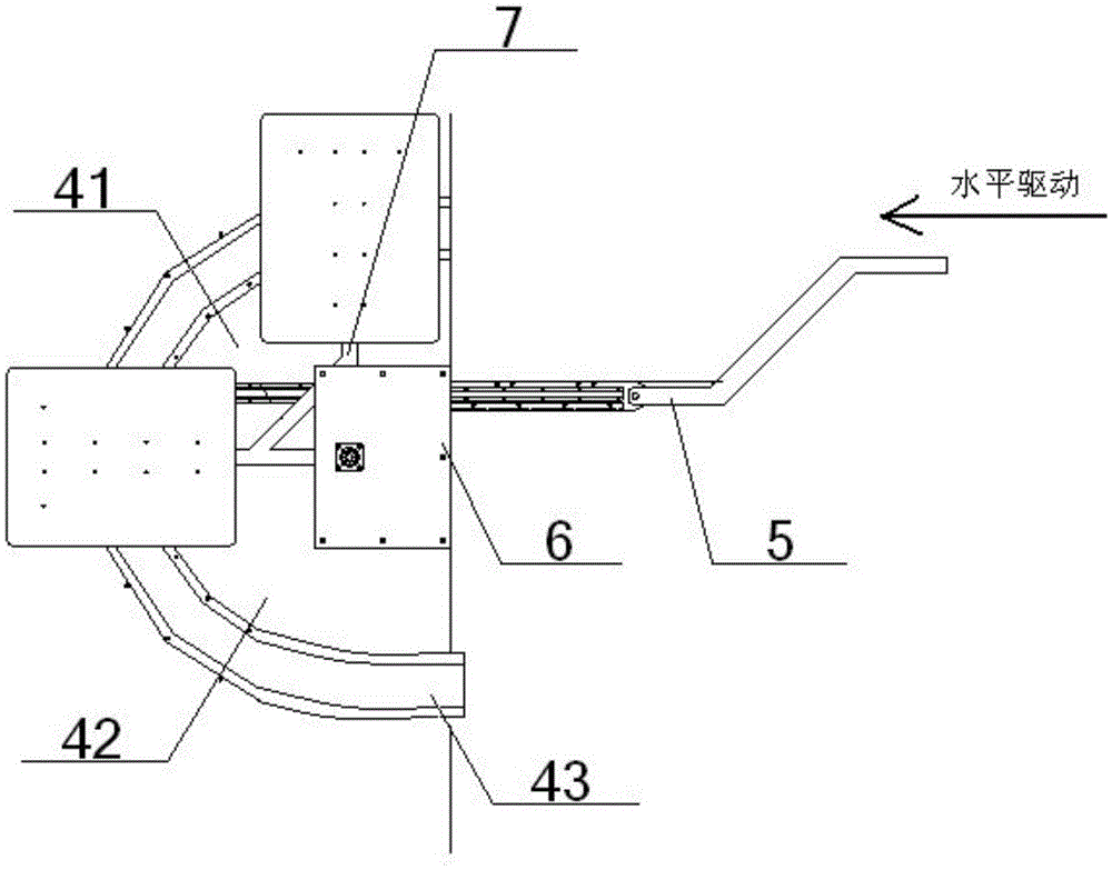
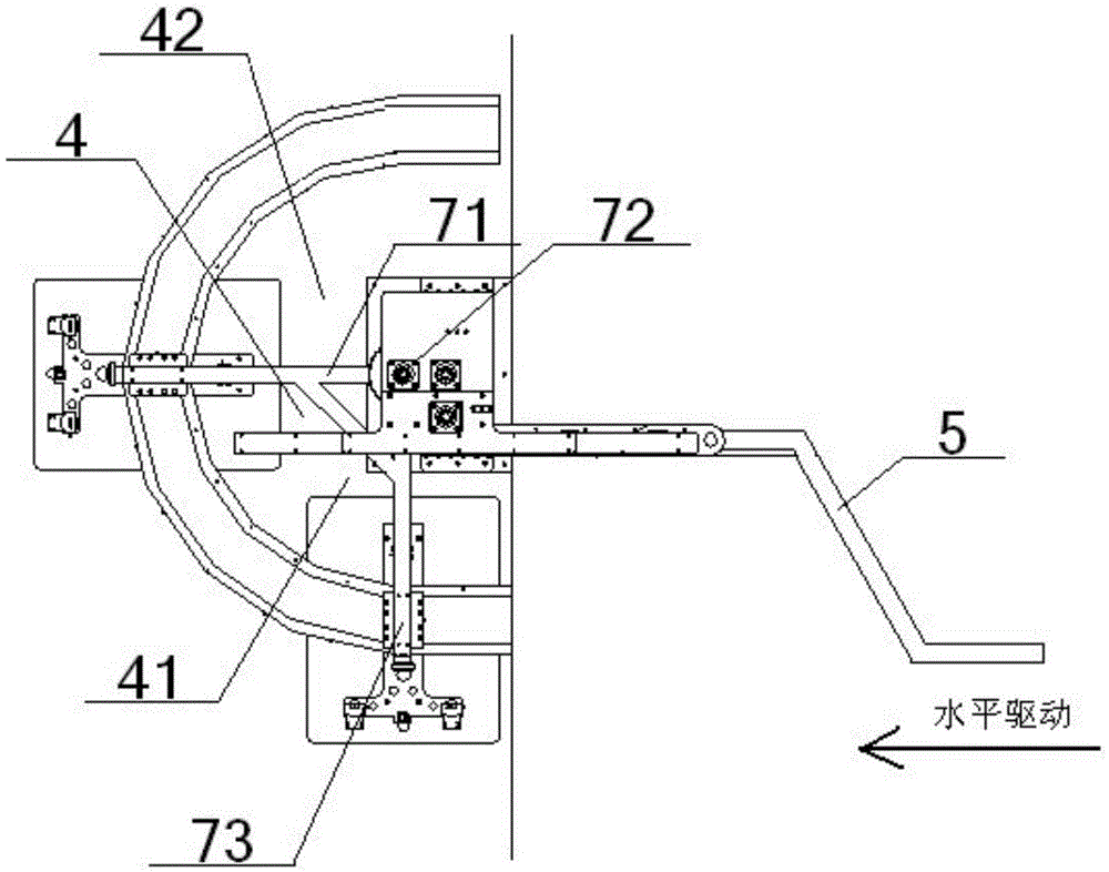
[0060] see figure 1 – Figure 14 , a turning type magnetic transmission device, comprising an arc-shaped table 4 and a printing table 2 arranged on it, the printing table 2 turns and rolls along the top surface of the arc-shaped table 4, and is arranged below the arc-shaped table 4 There is a turning drive device for the printing platen 2; the arc-shaped table 4 includes an active semi-arc surface 41 and a follow-up semi-arc surface 42 connected to each other as an integral structure, and a turning is provided below the active semi-arc surface 41 Type driving device, the turning type driving device includes a Z-shaped sub-frame 5, a gear transmission mechanism 6 and an L-shaped sub-frame 7. The L-shaped sub-frame 7 includes a horizontal rotation bracket 71, a rotation shaft 72 and a vertical rotation bracket 73. The top surface of one end of the rotating bracket 71 is connected with a horizontal rotating electromagnetic coil 711, the other end of the horizontal rotating brack...
Embodiment 2
[0064] Basic content is the same as embodiment 1, the difference is:
[0065] The gear transmission mechanism 6 includes a No. 1 large gear 61, a No. 2 large gear 62, a No. 2 gear shaft 63, a No. 3 gear shaft 64 and a rack 65, and the No. 1 large gear 61 is meshed with the No. 2 gear shaft 63 , the second gear shaft 63 is arranged coaxially with the second gear 62 directly above it, and the second gear 62 meshes with the rack 65 through the third gear shaft 64; the bottom surface of the rack 65 slides through the rack The rail seat 651 is slidingly matched with the rack slide rail 652, and one end of the rack 65 is connected with the upper horizontal end 51 of the Z-shaped sub-frame 5, and the other end of the rack 65 passes through the third pinion shaft 64 and the second large gear 62 in turn. , the No. 2 gear shaft 63 and the No. 1 large gear 61 are then coupled with the bottom end of the rotating shaft 72 , and the bottom of the rotating shaft 72 is positioned at the insid...
Embodiment 3
[0067] Basic content is the same as embodiment 1, the difference is:
[0068] The turning type magnetic transmission device also includes a straight table 1 and a plurality of printing tables 2 arranged on it, the printing table 2 rolls along the top surface of the straight table 1, and a printing table 2 is arranged below the straight table 1 The linear driving device 3, the linear driving device 3 includes a slide plate 31 and a plurality of electromagnetic coils 32, a linear guide rail 33, a guide rail seat 34, a support seat 35, the bottom of the electromagnetic coil 32 is connected with the top surface of the slide plate 31, The bottom surface of the slide plate 31 is connected with the top of the linear guide rail 33, and the bottom of the linear guide rail 33 is slidingly fitted with the guide rail seat 34 below it, and the bottom of the guide rail seat 34 is connected with the base plate 351 of the support seat 35 of the U-shaped structure. The seat side plate 352 vert...
PUM
 Abstract
Description
Claims
Application Information
 - R&D
- Intellectual Property
- Life Sciences
- Materials
- Tech Scout
- Unparalleled Data Quality
- Higher Quality Content
- 60% Fewer Hallucinations
Browse by: Latest US Patents, China's latest patents, Technical Efficacy Thesaurus, Application Domain, Technology Topic, Popular Technical Reports.
© 2025 PatSnap. All rights reserved.Legal|Privacy policy|Modern Slavery Act Transparency Statement|Sitemap|About US| Contact US: help@patsnap.com


