
Multi-axis aircraft

A multi-rotor aircraft and propeller technology, applied in the field of unmanned aerial vehicles, can solve the problems of aircraft flexibility and stability, low lift and weight of multi-axis aircraft, poor flexibility and stability of aircraft, etc., to improve the accuracy and sensitivity of remote control. Performance, simple and robust construction, the effect of improving flexibility and stability

Inactive Publication Date: 2016-05-25
浙江智天科技有限公司
View PDF6 Cites 17 Cited by
  • Summary
  • Abstract
  • Description
  • Claims
  • Application Information

AI Technical Summary

Problems solved by technology

The setting of the tripod on the multi-axis aircraft has a great influence on the flexibility and stability of the aircraft. The tripods of the existing multi-axis aircraft are basically fixed, and some tripods that can be folded can only be folded manually. After the aircraft takes off, the tripod cannot be retracted in time, so the flexibility and stability of the aircraft are poor. The lift of the multi-axis aircraft is related to the power of the motor and the length of the arm. The lift generated by the high-power motor is relatively large, but the high-power The motor consumes a lot of power, which requires very high battery performance and poor battery life; the longer the arm, the more motors can be installed, and the greater the lift that the motor can drive the propeller, but the length of the arm is limited Yes, so the lift and weight of ordinary multi-axis aircraft are relatively low, and the carrying capacity is limited when it is designed as a small aircraft

Method used


Image

  • Multi-axis aircraft
  • Multi-axis aircraft
  • Multi-axis aircraft

Examples


Embodiment 1

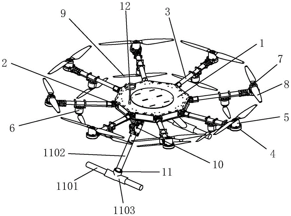
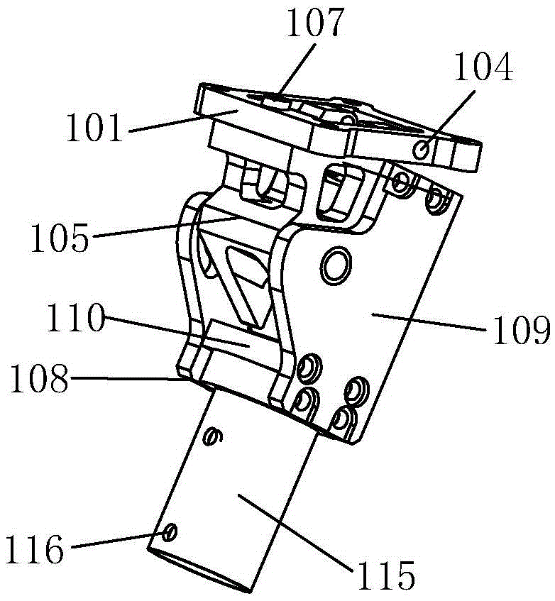
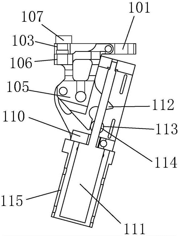
[0042] As shown in the figure, a multi-axis aircraft includes a frame 1, a pipe clamp 2, and a machine arm 3. The pipe clamp 2 is evenly distributed on the side of the frame 1, and the inner end of the machine arm 3 is connected with the pipe clamp 2. The machine arm 3. The outer end is provided with a motor seat 4, and the motor seat 4 is provided with a positive motor 5, and the middle of the machine arm 3 is provided with a reverse motor 6, and the rotating shafts of the normal motor 5 and the reverse motor 6 are provided with a propeller easy-to-install structure 7, and the normal The propeller easy-to-install structure 7 on the motor 5 is provided with a propeller 8, and the propeller 8 is located above the machine arm 3, and the propeller easy-to-install structure 7 on the motor 6 is provided with a reverse propeller 9, and the reverse propeller 9 is located on the machine arm. Below the arm 3, an electric tripod folding device 10 is provided at the bottom of the frame 1,...


PUM

PropertyMeasurementUnit
Lengthaaaaaaaaaa

Abstract

The invention belongs to the technical field of an unmanned aerial vehicle and specifically relates to a multi-axis aircraft. The multi-axis aircraft comprises a frame, a plurality of pipe clamps and an aircraft arm, wherein the pipe clamps are uniformly distributed on a side surface of the frame; an inner end of the aircraft arm is connected with the pipe clamps; a motor base is arranged at an outer end of the aircraft arm; a positive assembling motor is arranged in the motor base; a reversed assembling motor is arranged in the middle of the aircraft arm; a propeller easily assembled structure is respectively arranged on each of the revolving shafts of the positive assembling motor and the reversed assembling motor; a positive assembling propeller is arranged on the propeller easily assembled structure on the positive assembling motor; a reversed assembling propeller is arranged on the propeller easily assembled structure on the reversed assembling motor; an electric footstool foldable device is arranged at the bottom of the frame; and a footstool is connected with the electric footstool foldable device. The multi-axis aircraft can increase the generated lifting force within the limited volume size; the cruising power is higher; the manufacturing cost is lower; the structure is stable and firm; the sensitivity, the stability and the remote control precision are higher; the mounting and dismounting of each part are simple; and the multi-axis aircraft has competitive advantages in the competition process.

Description

technical field [0001] The invention belongs to the technical field of unmanned aerial vehicles, and in particular relates to a multi-axis aircraft. Background technique [0002] Multi-axis aircraft, that is, multi-rotor UAV, has multiple propellers, and multiple propellers are controlled by multiple motors to achieve flight. It is widely used in various fields such as aerial photography, monitoring, search and rescue, resource exploration, agriculture, etc. It has small size, It has the characteristics of light weight, low cost, flexible operation and high safety. The setting of the tripod on the multi-axis aircraft has a great influence on the flexibility and stability of the aircraft. The tripods of the existing multi-axis aircraft are basically fixed, and some tripods that can be folded can only be folded manually. After the aircraft takes off, the tripod cannot be retracted in time, so the flexibility and stability of the aircraft are poor. The lift of the multi-axis a...

Claims


Application Information

Patent Timeline
IPC IPC(8): B64C25/10B64C25/24B64C27/08B64C27/14B64C1/30B64D47/02
CPCB64C1/30B64C25/10B64C25/24B64C27/08B64C27/14B64D47/02B64U10/10
Inventor 陈灵峰
Owner 浙江智天科技有限公司
Learn More