
Intelligent transportation facility

A traffic facility, intelligent technology, applied in traffic signals, traffic restrictions, roads, etc., to achieve the effect of simple control process and widening lane width

Inactive Publication Date: 2016-05-25
HUNAN CITY UNIV
View PDF4 Cites 23 Cited by
  • Summary
  • Abstract
  • Description
  • Claims
  • Application Information

AI Technical Summary

Problems solved by technology

[0004] The purpose of the present invention is to provide a traffic facility that can intelligently control and automatically adjust the number of lanes in the uplink and downlink directions, and can solve the problem of road congestion that only occurs during specific periods of time at a lower cost

Method used


Image

  • Intelligent transportation facility
  • Intelligent transportation facility
  • Intelligent transportation facility

Examples


specific Embodiment 1

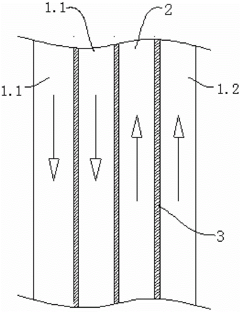
[0038] The road surface includes a left lane 1.1, a right lane 1.2, and a middle lane 2 whose driving direction can be changed. Both sides of the middle lane 2 are provided with traffic isolation devices 3 for distinguishing the driving direction of the lanes.

[0039] At 8 o'clock in the morning, there is a lot of traffic on the left lane 1.1, and the vehicle speed is relatively slow; lower the lifting pillar on the side of the middle lane 2 close to the lane 1.1, so that the vehicles on the lane 1.1 can use the middle lane 2 to drive , to increase the road speed and reduce the congestion on this road section.

[0040] At nine o'clock in the morning, the traffic flow on the lane 1.1 gradually decreases, and the lowered lifting ground column near the side of the lane 1.1 is raised on the middle lane 2, so that the lane width of the lane 1.1 is restored to its original state.

[0041] At 5 o'clock in the afternoon, there is a lot of traffic on the right lane 1.2, and the vehicl...

specific Embodiment 2

[0043] The road surface includes a lane 1.1 with a driving direction of the left and a lane 1.2 with a right driving direction, and a traffic separation device 3 for distinguishing the driving direction of the lanes is arranged between the lanes 1.1 and 1.2.

[0044] At 8 o'clock in the morning, there is a lot of traffic on the left lane 1.1, and the vehicle speed is relatively slow, and the lane 1.2 is basically free of vehicles; the lifting pillar on the side of lane 1.1 is lowered, so that the vehicles on lane 1.1 can borrow lane 1.2 Drive, increase the road speed, and reduce the congestion on this road section.

specific Embodiment 3

[0045] A traffic isolating device 3 is provided at a crossing where traffic is prohibited during a certain 7:30-19:30 time period.

[0046] From 7:30 to 19:30, the lifting column is raised to prohibit vehicles from passing; from 19:31 to 7:29 of the next day, the lifting column is lowered to allow vehicles to pass.


PUM


Abstract

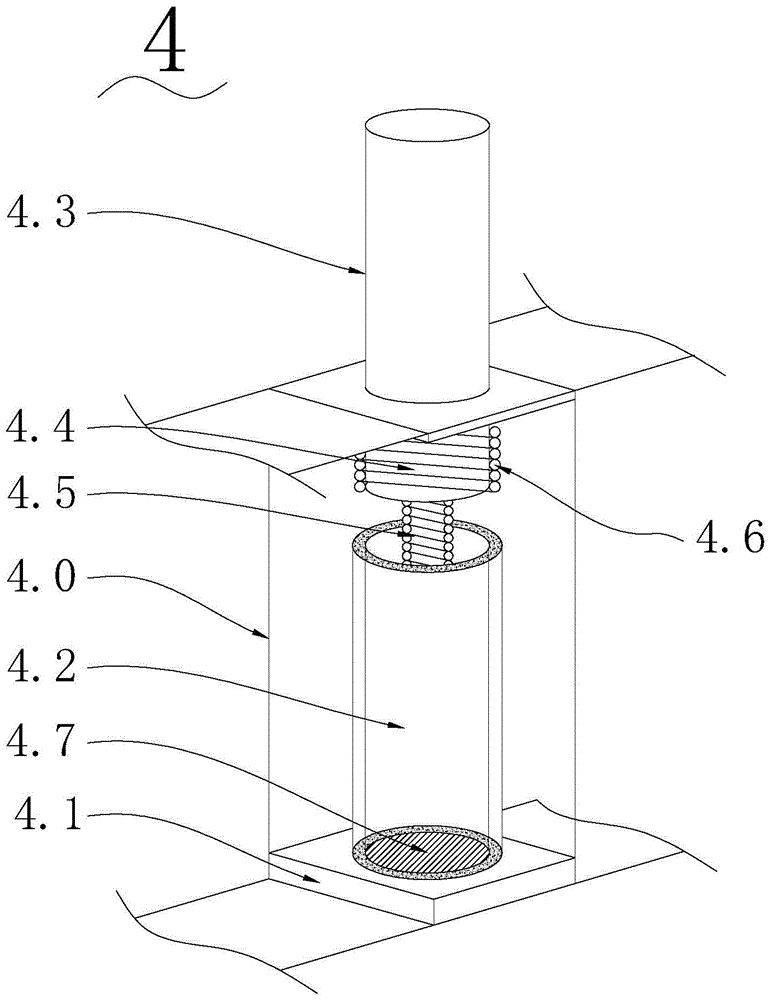
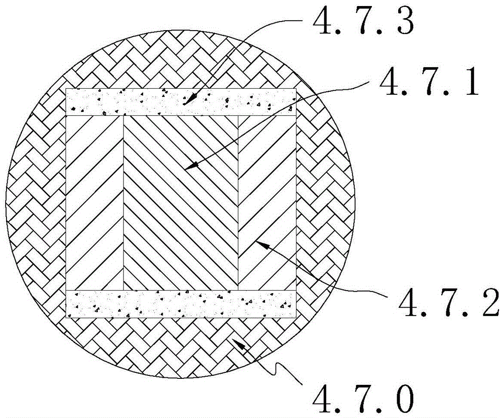
The invention provides an intelligent traffic isolation device which is characterized by comprising a plurality of automatic lifting columns, each automatic lifting column comprises an insulating box body mounted and embedded under the surface, a hollow insulating sleeve is arranged in the insulating box body and is fixedly connected with a bottom plate of the insulating box body, a lifting column body is movably sheathed inside a hollow cavity of the insulating sleeve, the bottom end of the lifting column body is an iron column, the upper end is anti-collision rubber, the outer surface of the iron column is connected with an electrified coil in a winding way, a permanent magnet corresponding to the iron column is arranged in the insulating sleeve, and a spring is connected between the bottom plate of the insulating box body and the lifting column body. When the lifting column body extends out of the surface, the iron column is positioned under the surface. The intelligent traffic isolation device provided by the invention can control and automatically regulate the quantity of lanes in the up-and-down direction and solve the road congestion problem occurring in specific time periods at a lower cost.

Description

technical field [0001] The invention relates to the field of transportation facilities, in particular, to an intelligent transportation facility. Background technique [0002] At present, automobiles have become the main means of transportation for urban residents. Urban residents usually work from Monday to Friday and rest on Saturday and Sunday. On weekends or other holidays, people hope to drive out of the city by themselves for rest and entertainment. Therefore, the situation that often occurs in the urban highway system is that on the first day of the holiday, the vehicles on the lanes in the direction of going out of the city are very crowded, and traffic jams often occur, while the lanes in the direction of entering the city have very few vehicles; On the last day, the inbound lanes were very crowded and the outbound lanes were light. Solving road congestion can be solved by building new roads, but it is unnecessary to build new roads connecting cities and suburbs ...

Claims


Application Information

Patent Timeline
IPC IPC(8): E01F13/04E01F9/669E01F9/619E01F15/00
CPCE01F13/046E01F15/006
Inventor 龙琼
Owner HUNAN CITY UNIV
Learn More