
Installation method of road fence with self-locking structure

A technology of self-locking structure and installation method, which is applied to road safety devices, roads, roads, etc., can solve the problems of difficult installation, long disassembly time, and many installation procedures, so as to reduce production costs, improve labor efficiency, and simplify the installation process Effect

Inactive Publication Date: 2016-05-25
JIANGSU SHUNDA TRAFFIC FACILITIES
View PDF6 Cites 6 Cited by
  • Summary
  • Abstract
  • Description
  • Claims
  • Application Information

AI Technical Summary

Problems solved by technology

[0002] The connection method between the upper rail and the upper rail connector of the road guardrail on the existing market has the following disadvantages in the process of installation and use: 1. If the upper rail and the upper rail connector are not fixed by any method, The overall strength of the guardrail is not strong. In the process of use, if a slight collision occurs, the guardrail mesh and the guardrail column will fall off, affecting the use and causing unfavorable factors for traffic.
2. If the connecting parts of the upper cross bar and the upper cross bar are fixed by bolts, there are many on-site installation procedures, the installation is difficult, and special tools are required for production. During use, after a collision occurs, special tools are required for guardrail maintenance , power supply, etc., the space for disassembling the bolts is narrow, which is easy to cause inconvenience to the maintenance personnel, and the disassembly time is long. If the bolts are rusted, it will increase the maintenance difficulty of the maintenance personnel, the maintenance man-hours will be more, and the maintenance cost will be increased. Big

Method used


Image

  • Installation method of road fence with self-locking structure
  • Installation method of road fence with self-locking structure

Examples


Embodiment Construction

[0014] Below in conjunction with accompanying drawing and embodiment the present invention is further described, and shown embodiment does not play any limitative effect to the content of invention described in claim, and, the whole content of the composition that following embodiment represents is not limited to as described in claim Necessary for the invented solution.

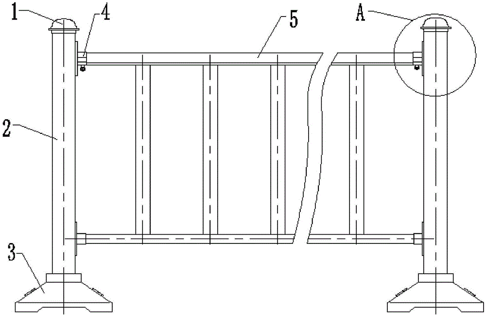
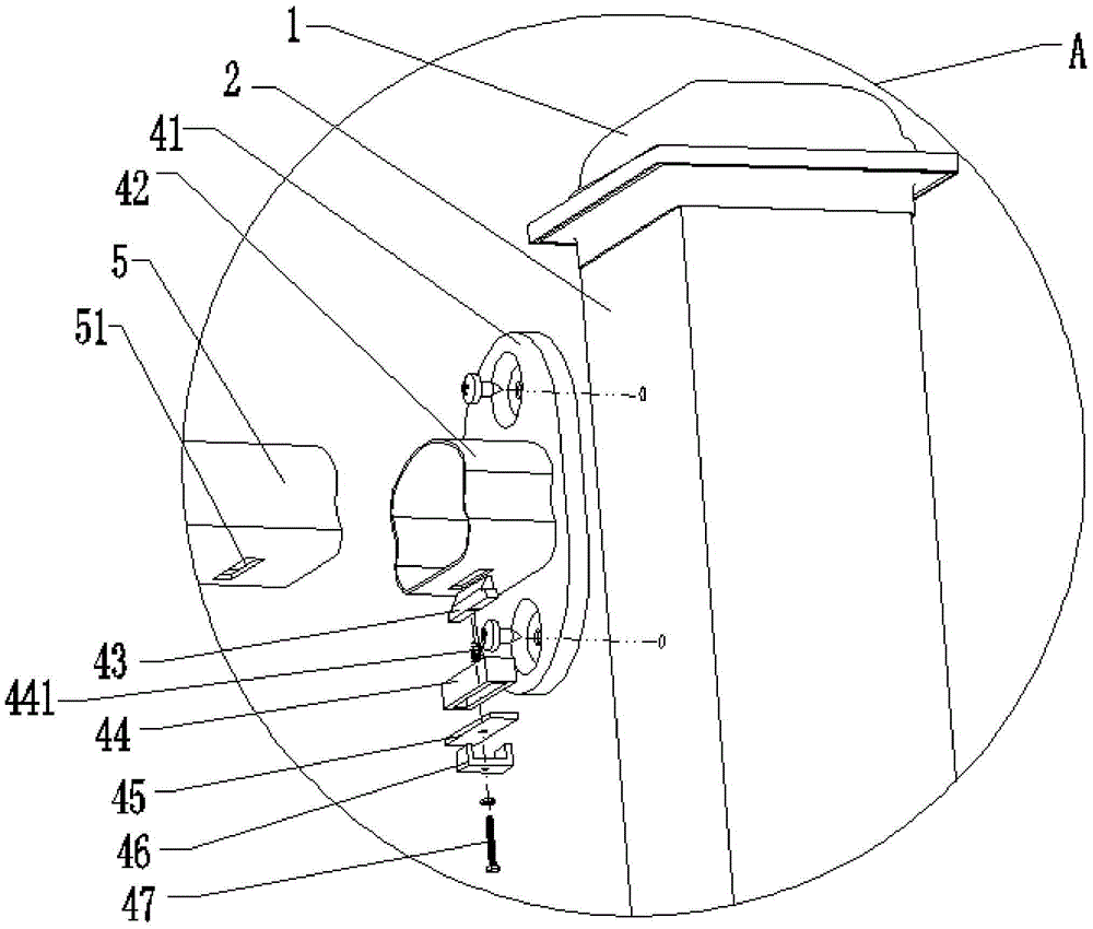
[0015] A road guardrail with a self-locking structure as shown in the accompanying drawings, the road guardrail includes: a connecting piece 4, a guardrail piece 5, a column 2 arranged at both ends of the guardrail piece 5, and a column arranged at the top and bottom of the column 2 respectively The cap 1 and the base 3, the two ends of the guardrail piece 5 are respectively connected to the column 2 through the connecting piece 4, and the said guardrail piece 5 includes: a vertical bar, an upper cross bar and a lower cross bar respectively arranged on the upper and lower parts of the vertical bar, and the co...


PUM


Abstract

The invention relates to an installation method of a road fence with a self-locking structure. The method specifically includes the steps that bolts sequentially penetrate through internal threads of nuts, rotation switch through holes, cover plate through holes, cushion block penetrating holes and slide block unequal-diameter holes from bottom to top to be connected into self-locking blocks, connection pieces are installed on stand columns through screws, fence pieces and the connection pieces are connected in an inserted mode, the slide blocks of the self-locking blocks are sequentially inserted in insertion openings and insertion grooves through spring elastic force of the self-locking blocks, the edges of the upper surfaces of cushion blocks are fixed to the bottoms of the fence pieces through welding, and therefore self-locking of the fence pieces and the connection pieces is achieved. The road fence is simple in structure, installation, self-locking and rapid detachment are integrated, time consumed during installation is short, the overall strength is high, the fence is not prone to falling in the collision process, the labor efficiency can be effectively improved, the possibility of accidents is lowered, the production cost is reduced, and the fence is convenient to use, practical and suitable for further application and popularization.

Description

technical field [0001] The invention relates to the technical field of structural design of road guardrail products, more specifically, relates to a method for installing a road guardrail with a self-locking structure. Background technique [0002] The connection method between the upper rail and the upper rail connector of the road guardrail on the existing market has the following disadvantages in the process of installation and use: 1. If the upper rail and the upper rail connector are not fixed by any method, The overall strength of the guardrail is not strong. In the process of use, if a slight collision occurs, the guardrail mesh and the guardrail column will fall off, affecting the use and causing unfavorable factors for traffic. 2. If the connecting parts of the upper cross bar and the upper cross bar are fixed by bolts, there are many on-site installation procedures, the installation is difficult, and special tools are required for production. During use, after a co...

Claims


Application Information

Patent Timeline
IPC IPC(8): E01F15/04
CPCE01F15/04E01F15/0484
Inventor 邹波
Owner JIANGSU SHUNDA TRAFFIC FACILITIES
Learn More