A valve camshaft device with cylinder deactivation engine

A camshaft and engine technology, applied in engine control, engine components, machines/engines, etc., can solve the problems of reduced conversion efficiency of nitrogen oxides, negative effects of engine emissions, and increased air volume, etc., to achieve easy promotion, excessive stability, The effect of fast axial movement speed

Inactive Publication Date: 2018-02-09
JILIN UNIV
View PDF5 Cites 0 Cited by
  • Summary
  • Abstract
  • Description
  • Claims
  • Application Information

AI Technical Summary

Problems solved by technology

[0003] However, when the engine adopts cylinder deactivation technology, if only the fuel injection and ignition of the deactivated cylinder are interrupted, the deactivated cylinder will still continue to intake and exhaust air, which will have a very bad negative impact on engine emissions
At present, most automobile engines use three-way catalytic converters to treat exhaust emissions. The three-way catalytic converters can only treat hydrocarbons, carbon monoxide and nitrogen oxides at the same time when the excess air ratio is around 1. Conversion efficiency, if the non-working cylinder continues to intake air, the air volume in the exhaust manifold of the engine will be greatly increased, the excess air coefficient will be much greater than 1, the conversion efficiency of nitrogen oxides in the exhaust will decrease significantly, and the emission will deteriorate

Method used


Image

  • A valve camshaft device with cylinder deactivation engine
  • A valve camshaft device with cylinder deactivation engine
  • A valve camshaft device with cylinder deactivation engine

Examples


Embodiment Construction

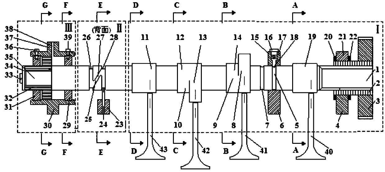
[0041] Combine below Figure 1-Figure 13 The present invention is described in detail.

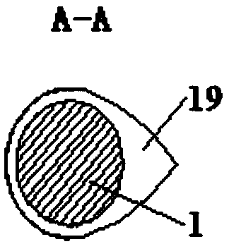
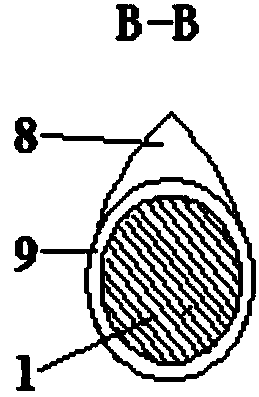
[0042] Such as figure 1 As shown, the present invention is composed of camshaft main system I, chute sliding system II and hydraulic control system III, valve guide rod a 40, valve guide rod c 41, valve guide rod d42 and valve guide rod b43, the camshaft main system Ⅰ. The chute sliding system Ⅱ and the hydraulic control system Ⅲ use the same camshaft 1, the camshaft main system Ⅰ is placed on the right part of the camshaft 1, the chute sliding system Ⅱ is placed in the middle of the camshaft 1, and the hydraulic control system Ⅲ is placed in the The left part of the camshaft 1, wherein the upper end of the valve guide rod a40 is slidingly connected with the cam a19 in the camshaft main system I, and the upper end of the valve guide rod b43 is slidingly connected with the cam b11 in the camshaft main system I.

[0043] When the positioning pin 18 in the camshaft main system I slides in t...


PUM


Abstract

The invention relates to a cylinder deactivation engine valve stop camshaft device, belonging to the technical field of engines. A hydraulic control system, a chute slide system and a camshaft main body system are respectively arranged on the left, middle and right parts of a camshaft, wherein the upper end of a valve guide rod a and a cam a form a slide connection, and the upper end of a valve guide rod b and a cam b form a slide connection. When a locating pin slides on a sliding chute a, the upper end of a valve guide rod c and a normal-contour cam a form a slide connection, and the upper end of a valve guide rod d and a normal-contour cam b form a slide connection. When the locating pin slides on a sliding chute b, the upper end of the valve guide rod c and a base-circle-contour cam a form a slide connection, and the upper end of the valve guide rod d and a base-circle-contour cam b form a slide connection. By using the camshaft device, the engine adopting the cylinder deactivation technique can implement no ventilation of the non-working cylinder, thereby ensuring the excess air coefficient of the exhaust, and giving consideration to the emission property of the cylinder deactivation engine. The cylinder deactivation engine valve stop camshaft device has the advantages of high control accuracy, smooth transition, simple structure and low cost, and is easy to manufacture and convenient for popularization.

Description

technical field [0001] The invention belongs to the technical field of engines, and in particular relates to a camshaft device for a cylinder-deactivated engine and a valve-deactivated camshaft. Background technique [0002] When the traditional automobile engine works under medium and small loads, the throttle opening is small and the pumping loss is large; the ventilation is not good, the residual exhaust gas in the engine cylinder is large, the combustion stability and integrity are poor, and the fuel consumption deteriorates. If the cylinder deactivation technology is adopted in the medium and small load conditions of a multi-cylinder engine, some cylinders will stop working. For example: in a four-cylinder engine, two cylinders will stop working. In order to ensure the same power output, the remaining working cylinders must increase the intake air volume and intake pressure. At the same time, the increase of intake pressure will also improve the charging efficiency of t...

Claims


Application Information

Patent Timeline
Patent Type & Authority Patents(China)
IPC IPC(8): F02D17/02F01L1/047
CPCF01L1/047F02D17/02
Inventor 解方喜洪伟苏岩李小平姜北平韩林沛钟兵
Owner JILIN UNIV
Why Eureka
Try Eureka