
Sand ultra-low frequency vibration sensor based on optical fiber array with lens

A technology of vibration sensor and lens optical fiber, which is applied in optical fiber sensing, devices in the field of environmental science and technology, and the field of wind and sand transport mechanics. It can solve the problems of complex system, unsuitable for measurement, expensive equipment, etc., and achieve strong light collection ability and modulation depth Ideal, light-receiving ability enhanced effect

Active Publication Date: 2018-08-14
SHANGHAI JIAO TONG UNIV
View PDF5 Cites 0 Cited by
  • Summary
  • Abstract
  • Description
  • Claims
  • Application Information

AI Technical Summary

Problems solved by technology

On September 15, 2011, the British "Nature" magazine published an article titled "Science enters desert debate" in the form of focus news, arguing that "currently people are mainly concerned with the monitoring and monitoring of soil erosion and grain production reduction caused by land degradation and desertification." Assessed, although scientists have conducted desertification research through satellite remote sensing data, these studies can only reflect macroscopic characteristics such as surface temperature and vegetation coverage. Next, scientists should start to look for the factors of land degradation and desertification and how they evolve.”
These technical means have their own strengths in measurement accuracy, but the system is complex and the equipment is expensive. They are mainly used in laboratories and are not suitable for measurement in desert sand and dust environments.

Method used


Image

  • Sand ultra-low frequency vibration sensor based on optical fiber array with lens
  • Sand ultra-low frequency vibration sensor based on optical fiber array with lens
  • Sand ultra-low frequency vibration sensor based on optical fiber array with lens

Examples


Embodiment Construction

[0031] A specific embodiment of the present invention is given below in conjunction with the accompanying drawings. This embodiment is implemented on the premise of the technical solution of the present invention, and detailed implementation methods and processes are given, but the protection scope of the present invention should not be limited to the following embodiments.

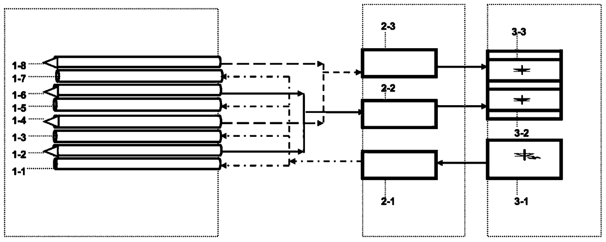
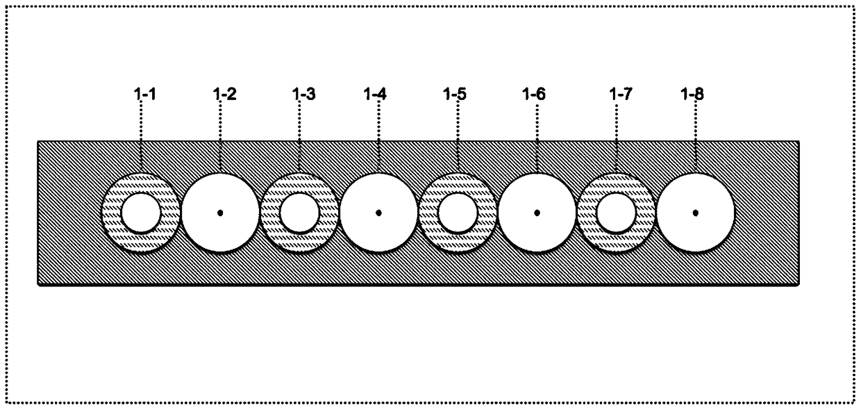
[0032] refer to figure 1 , the fiber array probe part includes a first multimode fiber 1-1, a first lens fiber 1-2, a second multimode fiber 1-3, a second lens fiber 1-4, a third Multimode fiber 1-5, the third lens fiber 1-6, the fourth multimode fiber 1-7, the fourth lens fiber 1-8; the optical splitter combiner part includes a 1X4 Optical splitter 2-1, the first 2X1 optical combiner 2-2, the second 2X1 optical combiner 2-3; the described light source and photodetector part includes the light source 3-1, the first photodetector A channel 3-2, a second channel 3-3 of the photodetector.

[0033]The ligh...


PUM


Abstract

The invention relates to a sand ultralow-frequency vibration sensor based on a lens-contained fiber array. The sensor is composed of an optical fiber array probe part, an optical branching and combiner part, and a light source and photoelectric detector part. The optical fiber array probe part consist of a first multimode fiber, a first lens fiber, a second multimode fiber, a second lens fiber, a third multimode fiber, a third lens fiber, a fourth multimode fiber, and a fourth lens fiber. The optical branching and combiner part includes a 1*4 optical branching unit, a second 2*1 optical combiner, and a second 2*1 optical combiner; and the light source and photoelectric detector part includes a light source, a first channel of a photoelectric detector, and a second channel of the photoelectric detector. According to the invention, because of the special arrangement way of the fiber array and the high light receiving capability of the tapered-lens-based fiber, detection of ultralow-frequency motion characteristics of small-sized particle objects like sands and PM2.5 particles can be realized.

Description

technical field [0001] The invention relates to a device in the fields of optical fiber sensing, wind and sand transport mechanics, and environmental science and technology, in particular to an ultra-low frequency vibration sensor for sand grains based on an optical fiber array with a lens. Background technique [0002] Sandstorm is a kind of extremely harmful global disaster weather phenomenon, which seriously threatens the safety of people's life and property. For example, on April 24, 2010, Minqin and other areas in Gansu Province were hit by a strong sandstorm, which caused more than 1.3 million people to be affected, 33,300 hectares of farmland failed to harvest, and the direct economic loss reached 937 million yuan. On September 15, 2011, the British "Nature" magazine published an article titled "Science enters desert debate" in the form of focus news, arguing that "currently people are mainly concerned with the monitoring and monitoring of soil erosion and grain produ...

Claims


Application Information

Patent Timeline
Patent Type & Authority Patents(China)
IPC IPC(8): G01H9/00G01P5/26
CPCG01H9/004G01P5/26
Inventor 马鑫李新碗陈建平邹卫文吴侃
Owner SHANGHAI JIAO TONG UNIV
Learn More