Lens adjusting structure and projection optic system

A projection optical system and technology for adjusting structure, which is applied in the field of lens adjustment structure and projection optical system, can solve the problems of increased energy loss of projection optical system, decrease of brightness performance of projection optical system, insufficient phosphor laser efficiency, etc., and achieves simple structure , use less parts, and prevent damage

Active Publication Date: 2016-05-25
CHINA HUALU GRP
View PDF8 Cites 11 Cited by
  • Summary
  • Abstract
  • Description
  • Claims
  • Application Information

AI Technical Summary

Problems solved by technology

[0003] A projector is a device that can project images or videos onto a screen. The key to determining the quality of the projection often lies in the optical system of the projector. The projection optical system in the prior art has the following problems: because the focal point of the laser light is relative to the fluorescent color The position of the phosphor coating of the wheel will always have a certain deviation, the laser efficiency of the phosphor is insufficient, the energy loss of the projection optical system will increase, and the brightness performance of the entire projection optical system will decrease

Method used


Image

  • Lens adjusting structure and projection optic system
  • Lens adjusting structure and projection optic system
  • Lens adjusting structure and projection optic system

Examples


Embodiment Construction

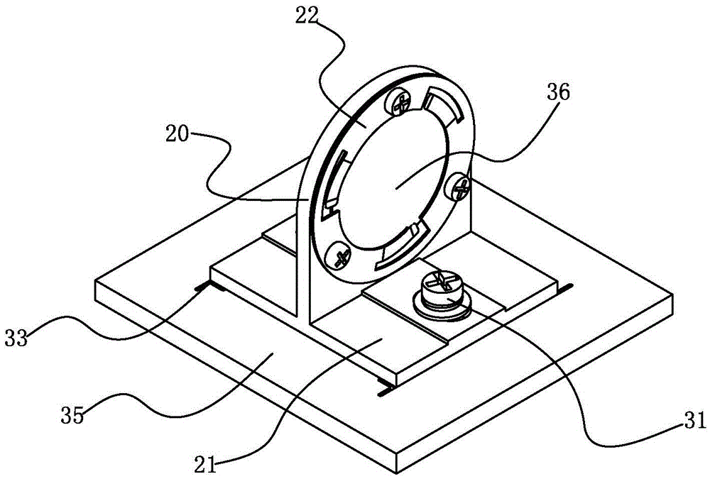
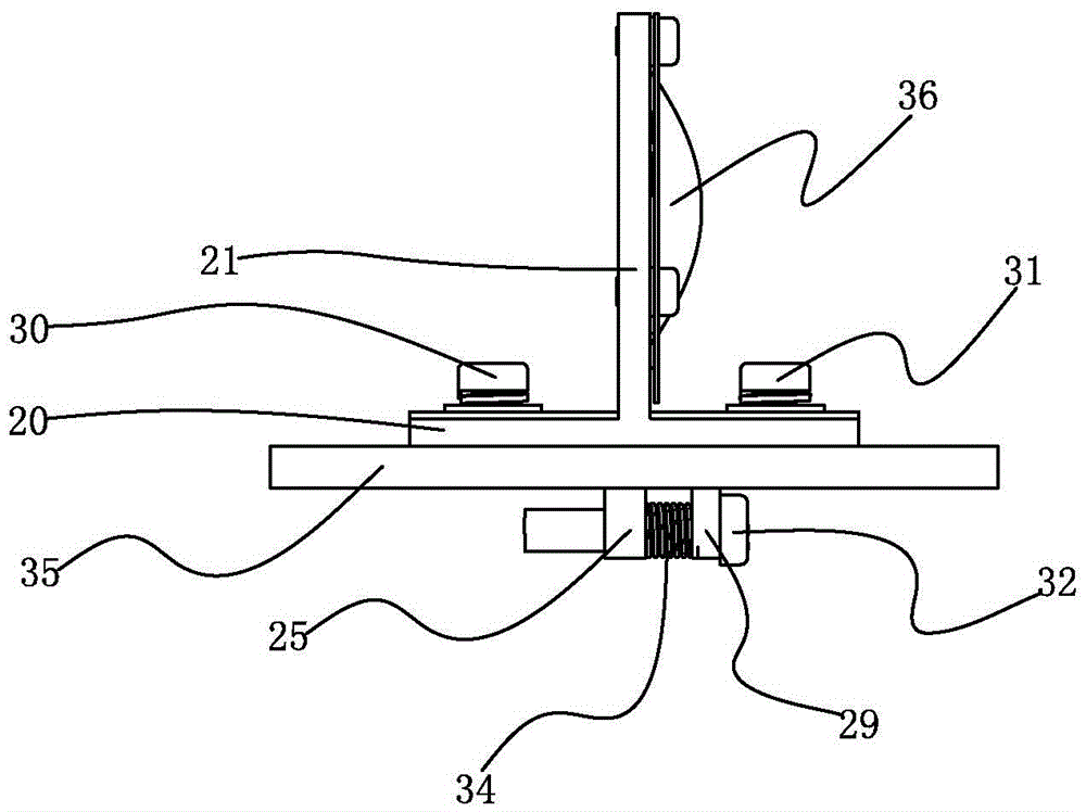
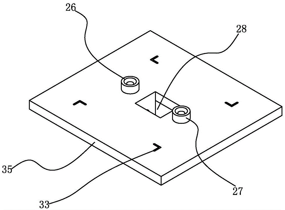
[0044] Such as figure 1 , figure 2 , image 3 , Figure 4 , Figure 5 and Figure 6 A lens adjustment structure shown includes: a lens holder, a base 35, a first pretensioner 30, a second pretensioner 31, an adjustment spring 34, and a fastener 32; the lens holder includes a horizontal adjustment part 20 and the support part 21 vertically placed on the adjustment part 20; the lens 36 is tightly pressed and fixed with the support part 21 through the annular pressing piece 22; The first guide hole 23 and the second guide hole 24 on both sides of the part 21; on the lower surface of the adjustment part 20, a first butt joint 25 between the first guide hole 23 and the second guide hole 24 protrudes. The adjustment part 20 is placed on the base 35 in a detachable manner; the base 35 has a first positioning member 26 and a second positioning member 27; A through opening 28 between a positioning piece 26 and a second positioning piece 27; a second butt joint 29 located on one...


PUM


Abstract

The invention discloses a lens adjusting structure and a projection optic system. The lens adjusting structure is composed of a lens holder, a pedestal, a first pre-tightening element, a second pre-tightening element, an adjusting spring, and a fastener. The lens holder includes an adjusting part and a support part; a first guide hole and a second guide hole that are formed in the two sides of the support part are arranged on the adjusting part; and a first butt-joint element arranged between the first guide hole and the second guide hole is arranged on the lower surface of the adjusting part in a protruding mode. A first positioning element and a second positioning element are arranged on the pedestal; a penetrating opening arranged between the first positioning element and the second positioning element is formed in the pedestal; and a second butt-joint element arranged at one side of the penetrating opening is arranged in the penetrating opening. According to the invention, problems that the energy is lost and the brightness performance of the overall projection optic system is reduced due to deviation of the position of the laser convergence point relative to the phosphor coating of the fluorescence color wheel in the existing optical system can be solved.

Description

technical field [0001] The invention relates to an optical element adjustment structure and an optical system with the optical element adjustment structure, in particular to a lens adjustment structure and a projection optical system. Background technique [0002] The optical system is a system composed of various optical elements in a certain order. It is generally used for imaging or optical processing. It can meet a series of requirements and obtain a high-quality optical system that meets the needs. It is not a simple combination of several optical elements. The parameters of each optical element must be reasonably configured and properly determined. In the prior art, due to errors in optical path calculation, mechanical processing technology, assembly technology, etc., the deviation of the optical system on the optical path is often caused, thereby affecting the performance of the optical system. As an important optical element in the optical system, the lens's positio...

Claims


Application Information

Patent Timeline
Patent Type & Authority Applications(China)
IPC IPC(8): G02B7/02G03B21/14G03B21/20
CPCG02B7/023G03B21/142G03B21/206
Inventor 杜健付瑶孙阳杨思文孔维成陈易
Owner CHINA HUALU GRP
Why Eureka
Try Eureka