Clamping and positioning device for robot welding positioner of large weldment and spring parameter selection method

A robot welding and positioning device technology, applied in auxiliary devices, welding equipment, auxiliary welding equipment, etc., can solve the problems of labor-consuming, time-consuming, efficiency, unsafe hidden danger, and affecting the quality of construction, positioning and installation.

Active Publication Date: 2016-06-01
YICHANG JIANGXIA MARINE MACHINERY
View PDF8 Cites 6 Cited by
  • Summary
  • Abstract
  • Description
  • Claims
  • Application Information

AI Technical Summary

Problems solved by technology

[0003] (1) It is not easy to control the size of the round hole when cutting the positioning round hole on the bottom surface of the workpiece with an air gun. When the gas cutting hole on the bottom surface of the workpiece is too large, accurate positioning cannot be performed. During the welding process, the large weldment will be rotated and displaced. Sliding, which will lead to inaccurate positioning of the welding robot, which will bring safety hazards and welding quality problems;
[0004] (2) If the positioning hole is too small during the gas cutting of the round hole on the base plate of the workpiece, the base plate of the large welded part will not be able to be installed, and it is necessary to repeatedly test pads of different thicknesses to adjust the leveling, which seriously affects the work efficiency, and it needs to be operated at high altitude. There are hidden dangers of insecurity and labor-intensive and time-consuming inefficiency;
[0005] (3) Due to the heavy weight of large welded parts, other auxiliary hoisting devices are needed in the process of positioning and clamping. The auxiliary hoisting devices are easily restricted by the spatial position relationship during use, which affects the quality of construction positioning and installation

Method used


Image

  • Clamping and positioning device for robot welding positioner of large weldment and spring parameter selection method
  • Clamping and positioning device for robot welding positioner of large weldment and spring parameter selection method
  • Clamping and positioning device for robot welding positioner of large weldment and spring parameter selection method

Examples


Embodiment 1

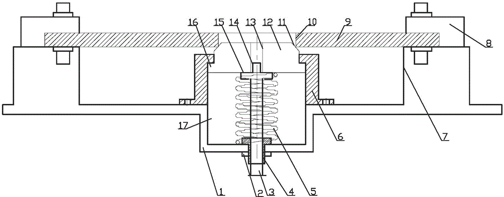
[0064] see figure 1 , a clamping and positioning device for a robot welding positioner for a large-scale weldment, it includes a housing 6, the housing 6 is fixed on the upper surface of the robot welding positioner 1 by bolts and is in contact with the cavity 17 of the positioner Cooperate to form a cylindrical cavity, the central position of the cylindrical cavity is equipped with a locking device 4 through a bolt, the inner of the locking device 4 is set with a clamping screw 3, and the outside of the clamping screw 3 is set with a spring 5; The lower end of the spring 5 is supported and fixed by the upper end surface of the cylindrical cavity, and the upper end is supported and fixed by the collar 15 of the clamping screw 3. The upper end of the collar 15 of the clamping screw 3 cooperates with the lower end surface of the floating cylinder 12, and the floating cylinder 12 is set In the interior of the housing 6 and through the positioning step 16, a positioning hole 13 is...

Embodiment 2

[0111] The following is the data under an actual working condition, and the selection process of the spring parameters through the above parameter selection method is as follows:

[0112] 1) According to the actual working conditions, the load of the floating cylinder 12 can be determined as: 290kg×9.8N / kg=2842N;

[0113] The total load of the workpiece and the floating cylinder 12 is: 2842N+15031kg×9.8N / kg=150127N;

[0114] Further preliminarily determine the minimum working load of spring 5 according to the above-mentioned parameters: P 1=4000N>2842N;

[0115] Maximum working load: P n =6000N<150127N;

[0116] Preliminarily determine the working stroke according to the distance between the housing 6 and the workpiece 9: h=50±1mm;

[0117] Preliminary determination of spring outer diameter according to the diameter of the collar 15: D' 2 ≈200mm;

[0118] The diameter of the spring material used is: d=20mm;

[0119] Spring category: N=103~106 times;

[0120] The end st...


PUM


Abstract

The invention relates to a clamping and positioning device for a robot welding positioner of a large weldment and a spring parameter selection method. Specific to uncertainty of hole site deviation of a bottom plate of a workpiece, main parameters of a spring are rapidly and conveniently determined through detailed spring stress calculation; and data are recorded and used for data comparison and lookup, and some judgments or conclusions are made. By means of the clamping and positioning device, the spring has an automatic adjusting function and the fixing function of a locking device, accuracy of automatic welding positioning of a robot is ensured, and reliable and fast positioning and clamping of the large weldment and the robot welding positioner are achieved.

Description

technical field [0001] The invention belongs to the field of robot welding positioner devices, and in particular relates to a clamping and positioning device and a spring parameter selection method of a robot welding positioner for large-scale welding parts, which improve welding accuracy and welding efficiency. Background technique [0002] At present, the operation method of the robotic welding positioner for clamping large-scale welded workpieces is to first gas-cut a round hole on the bottom plate of the large-scale welded part, and then cover the gas-cut circular hole on the bottom plate of the large-scale welded part on the fixed cylinder of the robot welding positioner. For positioning on the cone surface, the above-mentioned clamping positioning has the following defects and deficiencies: [0003] (1) It is not easy to control the size of the round hole when cutting the positioning round hole on the bottom surface of the workpiece with an air gun. When the gas cuttin...

Claims


Application Information

Patent Timeline
Patent Type & Authority Applications(China)
IPC IPC(8): B23K37/047F16F1/06F16F1/12
CPCB23K37/047F16F1/06F16F1/12
Inventor 何明朱明杨雄才刘志东
Owner YICHANG JIANGXIA MARINE MACHINERY
Why Eureka
Try Eureka